Stepper API Guide
Introduction

This guide will provide information about the Stepper API to get you up and running with your new Stepper Phidget.
Before starting this guide, visit the Quick Start Guide or User Guide on your Stepper Phidget's product page for information about wiring and power.
Guide Compatibility
Select your controller for compatibility information relating to this guide.
The 4A Stepper Phidget (STC1005_0) is fully compatible with this guide.
8A Stepper Phidget (STC1002_0) considerations:
- Fault, BadPower, and OverTemperature error events are not implemented on this device.
PhidgetStepper Bipolar HC (1067_0) considerations:
- Holding Current Limit functionality is not implemented for this device.
- Failsafe functionality is not implemented for this device.
- Fault, BadPower, and OverTemperature error events are not implemented on this device.
Stepper Phidget (STC1000_0) considerations:
- Fault, BadPower, and OverTemperature error events are not implemented on this device.
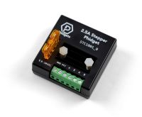
2.5A Stepper Phidget (STC1001_0) considerations:
- Fault, BadPower, and OverTemperature error events are not implemented on this device.
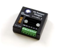
4A Stepper Phidget (STC1003_0) considerations:
- Fault, BadPower, and OverTemperature error events are not implemented on this device.
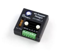
4A Stepper Phidget (STC1003_1) considerations:
- Fault, BadPower, and OverTemperature error events are not implemented on this device.
Stepper API Overview
Phidget Control Panel
After wiring your Stepper Phidget, we recommend opening the Phidget Control Panel on a Windows computer to experiment with key features.
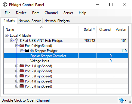
When the Stepper Phidget is powered, it will appear up on the Phidget Control Panel device list as shown above. Double-click on the Bipolar Stepper Controller entry to view the program.
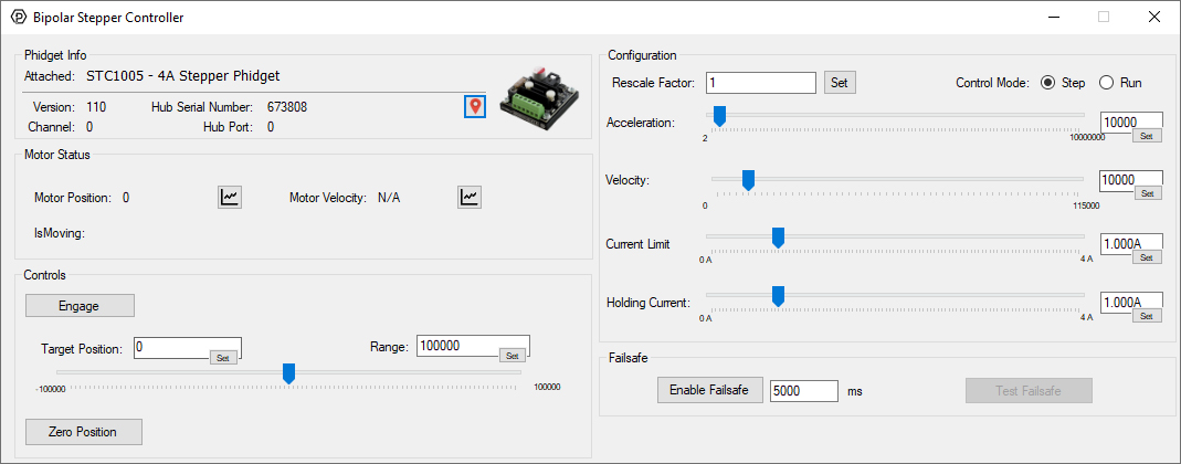
After opening the program, you will see the screen shown above. The program is split into multiple sections to help you get familiar with your motor controller.
- Phidget Info
- Motor Status
- Controls
- Configuration
- Failsafe
In this guide, we will focus on the areas that contain important information about controlling your Stepper. For information about the Phidget Info section, and the Phidget Control Panel in general, visit our Phidget Control Panel Page.
Configuration
Rescale Factor
The Rescale Factor allows you to change the units of the following properties:
All modern Phidget stepper controller have default units of 1/16 steps per count, which is not intuitive. We recommend utilizing the Rescale Factor so your software is easier to understand.
Example Calculations
Generally, most users will prefer units of degrees or rotations. To determine an appropriate Rescale Factor, you will need to know the following values:
- Step angle of the motor
- Gear ratio (if applicable)
- If you are purchasing a motor from Phidgets Inc., the exact fractional gear ratio can be found in the specification table on the product page. This is more precise than the ratio found in the product name or other marketing material.
Converting to Degrees
Specifications of system:
- Step angle: 1.8°
- Gear ratio: 15 3/10 : 1 = 15.3 : 1
Rescale Factor = 1.8 / (16 * 15.3) = 0.007353
Converting to Rotations
Specifications of system:
- Step angle: 1.8°
- Gear ratio: 15 3/10 : 1 = 15.3 : 1
Rescale Factor = 1.8 / (16 * 15.3 * 360) = 0.00002042
Control Mode
The Control Mode changes how your controller moves your motor. There are two modes to choose from:
- Step Mode (default behavior)
- Run Mode
Step Mode
Step Mode is the default behavior. In this mode, you specify a Target Position that the controller will attempt to reach.
Run Mode
In Run Mode, you specify a Velocity Limit and the motor will rotate continuously. The motor will rotate in one direction if the Velocity Limit is positive, and in the opposite direction if the Velocity Limit is negative.
Other Considerations
The Control Mode should not be modified while the controller is Engaged.
Acceleration
Acceleration directly controls how quickly your controller will adjust its Velocity.
Examples
In these examples, a Rescale Factor has been applied to the controller to change the units to rotations.
| Initial Velocity (rotations/s) |
Velocity Limit (rotation/s) |
Time to Reach Velocity Limit |
|---|---|---|
| 0.0 | 1.0 | 1 second |
| Initial Velocity (rotation/s) |
Velocity Limit (rotations/s) |
Time to Reach Velocity Limit |
|---|---|---|
| 0.0 | 1.0 | 10 seconds |
Other Considerations
- Your motor may not be able to achieve the set Acceleration due to physical limitations. In these situations, the motor will often fall out of sync with the controller, and a stall will occur.
- We recommend determining an appropriate Velocity Limit for your application and then increasing the Acceleration until you achieve repeatable results from your system.
- Acceleration applies when your controller is attempting to accelerate and decelerate your motor.
- Acceleration should only be modified while the motor is disengaged.
- You can use the Rescale Factor to modify the base units of this property.
Velocity Limit
The controller allows you to configure a Velocity Limit for your motor.
Other Considerations
- The controller receives no feedback from the motor, so external forces may cause your motor to exceed the Velocity Limit.
- The motor may not be able to reach the Velocity Limit due physical limitations. In these situations, the motor will often fall out of sync with the controller, and a stall will occur.
- You can use the Rescale Factor to modify the base units of this property.
Current Limit
Current limiting is an advanced, yet easy-to-use feature that intelligently monitors and controls the current through your motor.
Determining Your Current Limit
The datasheet of your motor will specify a Rated Current. Set your current limit to a value less than or equal to the rated current for your motor.
Other Considerations
You can specify a Holding Current Limit that will supersede the Current Limit when your motor is stopped.
Holding Current Limit
The Holding Current Limit monitors and controls the current through your motor when the motor is stopped and engaged. This allows you to hold your motor position more aggressively while stopped without using your entire current limit which can result in overheating of your motor.
Determining Your Holding Current Limit
Use the Phidget Control Panel and start with a non-zero Holding Current Limit (e.g. 0.1A). Slowly increase the value until you achieve the required holding strength for your application. You can then hardcode this value into your final application.
Other Considerations
- If a Holding Current Limit is not specified, the Current Limit will persist when the motor is stopped and engaged.
- If your application does not need to hold position while stopped, we recommend disengaging your controller.
Motor Status
Motor Position
The most recent Position value reported by the controller.
Other Considerations
- The default units of position are 1/16th steps. You can use the Rescale Factor to modify the units of this property.
- The controller receives no feedback from the motor, so the Position value may not accurately describe the actual position of your motor.
- You can Zero Position to reset the Position count.
- You can modify the
DataIntervalorDataRateto receive Position updates more or less often. These are not available to modify through the Phidget Control Panel example.
Motor Velocity
The most recent Velocity value reported by the controller.
Other Considerations
- The default units of Velocity are 1/16th steps per second. You can use the Rescale Factor to modify the units of this property.
- The controller receives no feedback from the motor, so the Velocity value may not accurately describe the velocity of your motor.
- You can modify the
DataIntervalorDataRateto receive Velocity updates more or less often. These are not available to modify through the Phidget Control Panel example.
isMoving
If the controller is actively sending commands to the motor, the isMoving property will be true. When the controller has stopped sending commands, the Stopped event will fire.
In the Phidget Control Panel program, this can be seen via the isMoving label which will display Moving with a green background when commands are being sent, and Stopped with a red background when the controller has stopped sending commands.
Other Considerations
The controller receives no feedback from the motor, so this label may not always reflect reality.
Controls
Engage/Disengage
The controller is disengaged by default. When disengaged, no power is being supplied to the motor, no current limits are adhered to, and the motor shaft will rotate freely.
In Step Mode, a Target Position must be set or the controller will remain disengaged. In Run Mode, the controller will be active after engage has been set, no other values require setting.
Target Position
When the controller is Engaged, it will attempt to reach the Target Position.
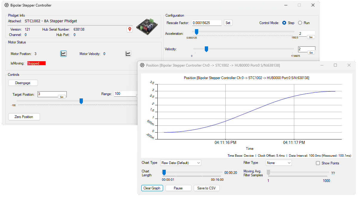
Motion Profiling
Trapezoidal motion profiling is used in order to achieve the Target Position. This allows for advanced control and improved repeatability of your system. Trapezoidal motion profiling is named for the trapezoidal shape of the Velocity-Time graph (shown below in orange).
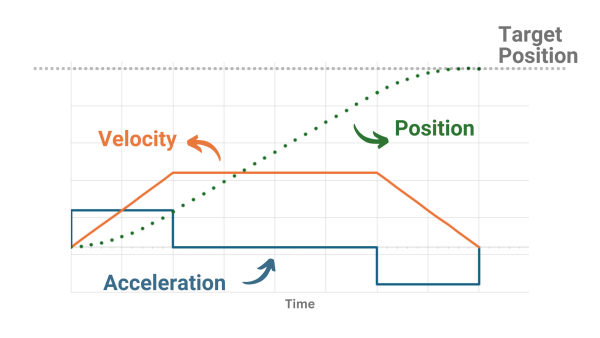
The controller will follow the user-specified acceleration and velocity limit to determine the motor's position. We can see this when viewing a graph of the controller's Position:
Units
By default, the Target Position units are in 1/16th steps. For example, if your motor has a step angle of 0.9° and no gearbox, you would have to set your Target Position to 6400 to rotate your motor shaft one full revolution.
You can use the Rescale Factor to modify the base units of this property.
Other Considerations
- Target Position is only applicable when in Step Mode.
- The controller must be Engaged or it will not attempt to reach the Target Position.
Zero Position
This button will zero your Position. It uses the addPositionOffset method in the API.
Failsafe
Failsafe is a feature that, when activated, will disengage the motor if it hasn't had communication with your program for a specified period of time. For more information, view our Failsafe Guide.
Errors
If the error you are looking for is not mentioned below, please visit the API for your controller.
BadPower
New Phidget Stepper controllers include onboard sensing of the supply voltage.
| Input Voltage During Operation (VDC) | Result |
|---|---|
| 10-30 | Normal operation |
| < 10 | Bad Power error condition. This can happen for many reasons, including a bad power supply or a motor that is drawing excessive current. |
| > 30 | Bad Power error condition may occur. This can happen for many reasons, including a bad power supply. |
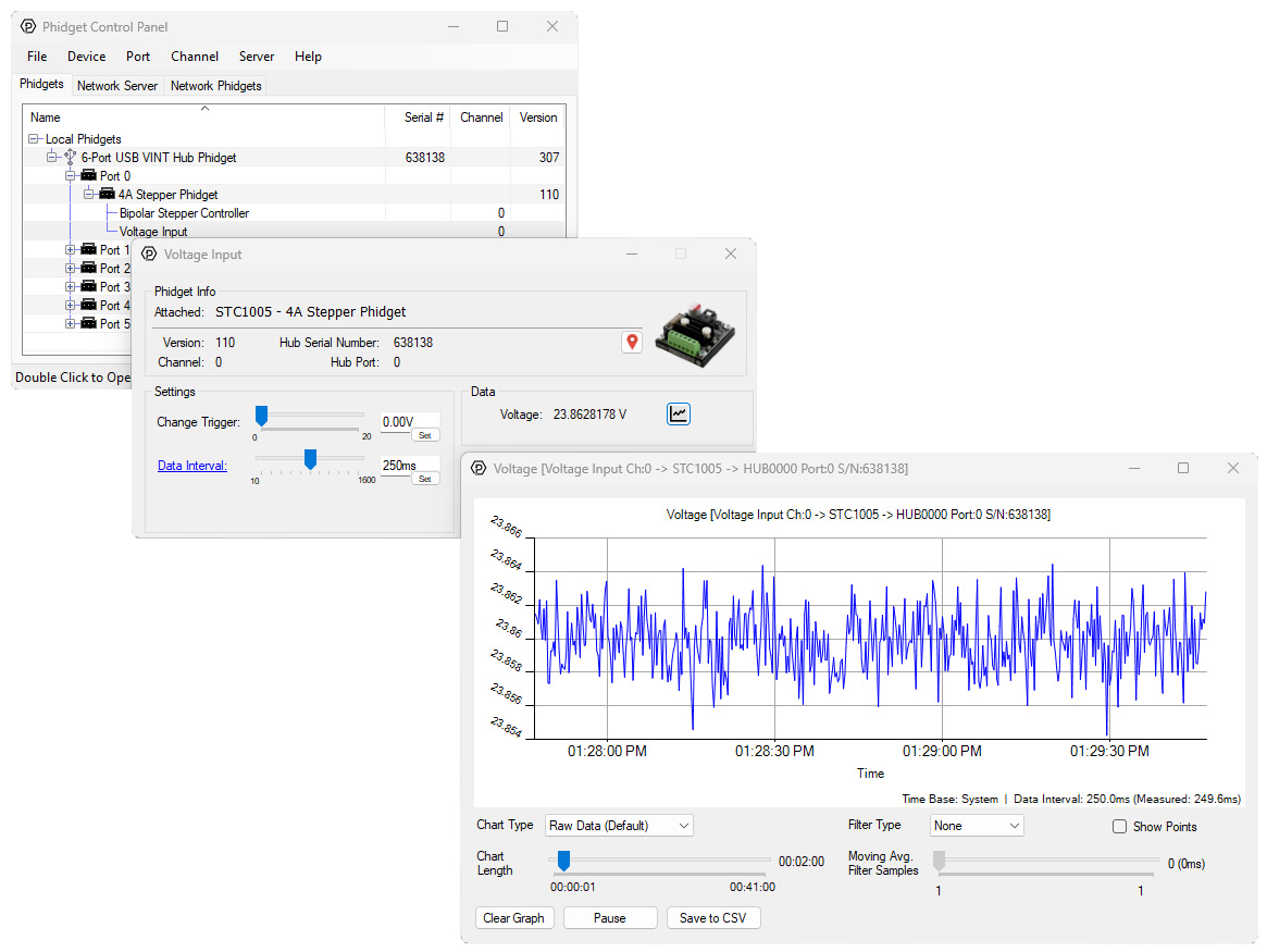
Monitoring Supply Voltage
If your application is experiencing BadPower errors, consider using the built-in Voltage Input channel to monitor your power supply. The Phidget Control Panel on Windows has a graphing feature that can help diagnose issues. A typical 24V power supply is shown below.
Fault
This error indicates that the controller has detected a fault. This usually occurs when the motor stalls at high speeds. The controller will not detect all stalls. For applications where stall-detection is required, we recommend using an encoder.
OverTemperature
This error triggers when the controller's temperature exceeds its predetermined limits. If your application consistently experiences OverTemperature errors, consider lowering the Current Limit and/or adding additional cooling to your system (e.g. fans, larger heatsink, etc.).
Failsafe (Error Event)
This error indicates that a Failsafe state has been triggered. For more information, view our Failsafe Guide.