RCC1000 User Guide: Difference between revisions
No edit summary |
No edit summary |
||
| (7 intermediate revisions by 2 users not shown) | |||
| Line 1: | Line 1: | ||
__NOINDEX__ | __NOINDEX__ | ||
__NOTOC__ | |||
<metadesc>Control up to 16 servo motors from a single VINT port using the 16x Servo Phidget.</metadesc> | <metadesc>Control up to 16 servo motors from a single VINT port using the 16x Servo Phidget.</metadesc> | ||
[[Category:UserGuide]] | [[Category:UserGuide]] | ||
=== | ==Part 1: Setup== | ||
{{PT1 Deck Sequence}} | |||
== Part 2: Using Your Phidget == | |||
===About=== | |||
The RC Servo Phidget can control the position, velocity, and acceleration of up to 16 RC servo motors. It is powered externally by an 8-30V supply, providing a total of up to 20A of regulated power to its servos. You can control the regulator and choose a global voltage of 5.0V, 6.0V, or 7.4V. A servo will have more torque when running at a higher voltage but will have a shorter overall lifespan. | |||
[[Image:RCC1000_About.jpg|link=]] | |||
==Using | ===Explore Your Phidget Channels Using The Control Panel=== | ||
You can use your Control Panel to explore your Phidget's channels. | |||
'''1.''' Open your Control Panel, and you will find the following channels: | |||
= | [[Image:RCC1000_Panel.jpg|link=|center]] | ||
'''2.''' Double click on a channel to open an example program. Each channel belongs to the '''RCServo''' channel class: | |||
{{UGC-Start}} | |||
{{UGC-Entry|RC Servo Motor Controller:| Controls the position, velocity limit, acceleration and supply voltage of a servo motor| | |||
In your Control Panel, double click on "RC Servo Motor Controller": | |||
= | [[Image:RCC1000-RCServo.jpg|center|link=|800px]]}} | ||
{{UGC-End}} | |||
{{UG-Part3}} | |||
== Part 4: Advanced Topics and Troubleshooting == | |||
{{UGC-Start}} | |||
{{UGC-Addressing}} | |||
{{UGC-Firmware}} | |||
{{UGC-Entry|Selecting Min and Max Pulse Width|| | |||
The easiest way to determine the minimum and maximum pulse width is to check your servo's datasheet or specification table and use the numbers provided. If you do not have the numbers, you can determine the maximum and minimum pulse width by following this process: | |||
*Set the minimum to 1000us and the maximum to 1001us as a starting point | |||
*Reduce the minimum to 900us and hit apply. Enable the servo and test moving to the minimum position value, and then return to the maximum. If the servo doesn’t vibrate or make a buzzing noise, you can continue to reduce the minimum and repeat this process. | |||
*When the servo eventually vibrates or makes a buzzing noise, it means it's stalled out and you've gone past its minimum. If this happens, continue increasing the minimum by small amounts until there is no buzzing or vibration when holding the minimum position. | |||
*Repeat this process for the maximum pulse width, increasing the maximum setting until the motor stalls out. Then adjust lower to hit the maximum value without the motor stalling. | |||
This process is important because selecting a minimum or maximum pulse width that results in the motor stalling could have an impact on the motor's lifespan. | |||
If you have a continuous rotation servo, you do not have to worry about the motor stalling. Increase the maximum and decrease the minimum until you reach the servo's maximum speed. | |||
Many applications call for several servo motors operating in unison - for example, operating a CNC table, or a robot arm. Highly precise synchronization of servos using the RCC1000 is not possible, as the sequencing will be affected by the real-time performance of your operating system. Each servo is controlled as | }} | ||
{{UGC-Entry|Synchronization of Multiple Servo Motors|| | |||
Many applications call for several servo motors operating in unison - for example, operating a CNC table, or a robot arm. Highly precise synchronization of servos using the RCC1000 is not possible, as the sequencing will be affected by the real-time performance of your operating system. Each servo is controlled as an independent unit, so there is no way of arranging for a particular action to happen to all motors at the same time. Typical jitter can be 10-30mS. | |||
}} | |||
{{UGC-End}} | |||
{{ | |||
Latest revision as of 16:27, 3 July 2024
Part 1: Setup
Part 2: Using Your Phidget
About
The RC Servo Phidget can control the position, velocity, and acceleration of up to 16 RC servo motors. It is powered externally by an 8-30V supply, providing a total of up to 20A of regulated power to its servos. You can control the regulator and choose a global voltage of 5.0V, 6.0V, or 7.4V. A servo will have more torque when running at a higher voltage but will have a shorter overall lifespan.

Explore Your Phidget Channels Using The Control Panel
You can use your Control Panel to explore your Phidget's channels.
1. Open your Control Panel, and you will find the following channels:
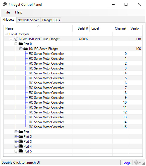
2. Double click on a channel to open an example program. Each channel belongs to the RCServo channel class:
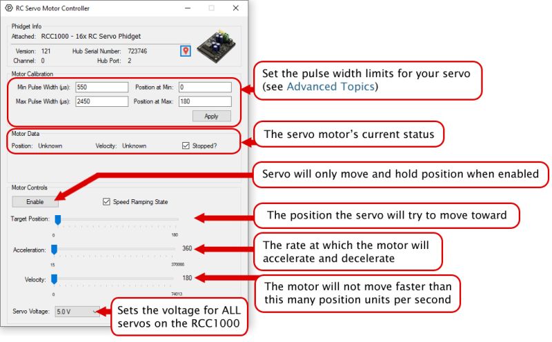
In your Control Panel, double click on "RC Servo Motor Controller":
Part 3: Create your Program
Part 4: Advanced Topics and Troubleshooting
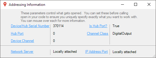
Before you open a Phidget channel in your program, you can set these properties to specify which channel to open. You can find this information through the Control Panel.
1. Open the Control Panel and double-click on the red map pin icon:

2. The Addressing Information window will open. Here you will find all the information you need to address your Phidget in your program.
See the Phidget22 API for your language to determine exact syntax for each property.
Firmware Upgrade
MacOS users can upgrade device firmware by double-clicking the device row in the Phidget Control Panel.
Linux users can upgrade via the phidget22admin tool (see included readme for instructions).
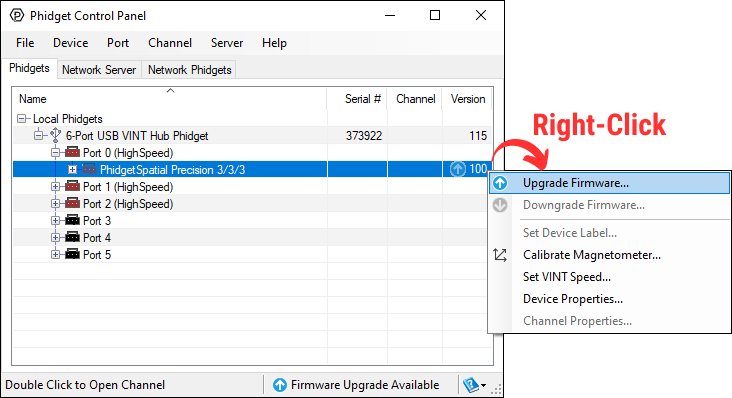
Windows users can upgrade the firmware for this device using the Phidget Control Panel as shown below.
Firmware Downgrade
Firmware upgrades include important bug fixes and performance improvements, but there are some situations where you may want to revert to an old version of the firmware (for instance, when an application you're using is compiled using an older version of phidget22 that doesn't recognize the new firmware).
MacOS and Linux users can downgrade using the phidget22admin tool in the terminal (see included readme for instructions).
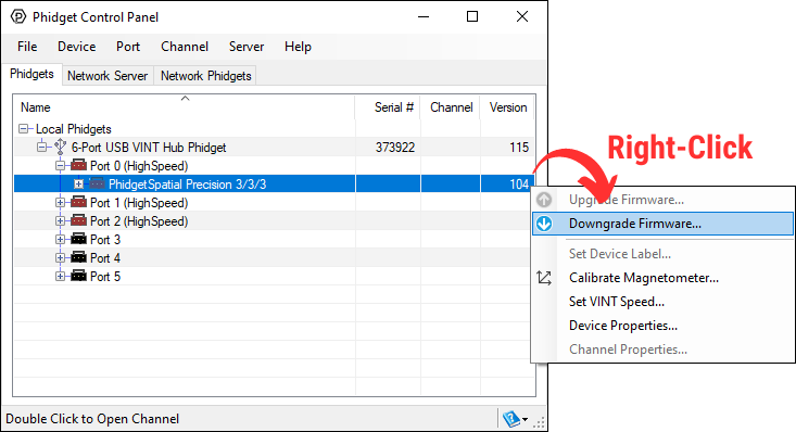
Windows users can downgrade directly from the Phidget Control Panel if they have driver version 1.9.20220112 or newer:
Firmware Version Numbering Schema
Phidgets device firmware is represented by a 3-digit number. For firmware patch notes, see the device history section on the Specifications tab on your device's product page.
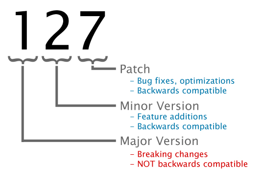
- If the digit in the 'ones' spot changes, it means there have been bug fixes or optimizations. Sometimes these changes can drastically improve the performance of the device, so you should still upgrade whenever possible. These upgrades are backwards compatible, meaning you can still use this Phidget on a computer that has Phidget22 drivers from before this firmware upgrade was released.
- If the digit in the 'tens' spot changes, it means some features were added (e.g. new API commands or events). These upgrades are also backwards compatible, in the sense that computers running old Phidget22 drivers will still be able to use the device, but they will not be able to use any of the new features this version added.
- If the digit in the 'hundreds' spot changes, it means a major change has occurred (e.g. a complete rewrite of the firmware or moving to a new architecture). These changes are not backwards compatible, so if you try to use the upgraded board on a computer with old Phidget22 drivers, it will show up as unsupported in the Control Panel and any applications build using the old libraries won't recognize it either. Sometimes, when a Phidget has a new hardware revision (e.g. 1018_2 -> 1018_3), the firmware version's hundreds digit will change because entirely new firmware was needed (usually because a change in the processor). In this case, older hardware revisions won't be able to be upgraded to the higher version number and instead continue to get bug fixes within the same major revision.
The easiest way to determine the minimum and maximum pulse width is to check your servo's datasheet or specification table and use the numbers provided. If you do not have the numbers, you can determine the maximum and minimum pulse width by following this process:
- Set the minimum to 1000us and the maximum to 1001us as a starting point
- Reduce the minimum to 900us and hit apply. Enable the servo and test moving to the minimum position value, and then return to the maximum. If the servo doesn’t vibrate or make a buzzing noise, you can continue to reduce the minimum and repeat this process.
- When the servo eventually vibrates or makes a buzzing noise, it means it's stalled out and you've gone past its minimum. If this happens, continue increasing the minimum by small amounts until there is no buzzing or vibration when holding the minimum position.
- Repeat this process for the maximum pulse width, increasing the maximum setting until the motor stalls out. Then adjust lower to hit the maximum value without the motor stalling.
This process is important because selecting a minimum or maximum pulse width that results in the motor stalling could have an impact on the motor's lifespan.
If you have a continuous rotation servo, you do not have to worry about the motor stalling. Increase the maximum and decrease the minimum until you reach the servo's maximum speed.
Many applications call for several servo motors operating in unison - for example, operating a CNC table, or a robot arm. Highly precise synchronization of servos using the RCC1000 is not possible, as the sequencing will be affected by the real-time performance of your operating system. Each servo is controlled as an independent unit, so there is no way of arranging for a particular action to happen to all motors at the same time. Typical jitter can be 10-30mS.
