Thermocouple Guide: Difference between revisions
No edit summary |
|||
| (17 intermediate revisions by 3 users not shown) | |||
| Line 1: | Line 1: | ||
[[Category: | {{#seo:|description=Thermocouples let you measure a wide temperature range. This guide explains the basics: how thermocouples work, how to choose a thermocouple, how to connect a thermocouple and more.}} | ||
{{#seo:|keywords=thermocouple, temperature}} | |||
[[Category:IntroGuide]] | |||
<div class="toclimit-3">__TOC__</div> | |||
==Introduction== | ==Introduction== | ||
[[File:TMP4103_0_Web.jpg|link=|right|400px]] | |||
A thermocouple is a device consisting of 2 different conductors that produce a voltage proportional to a temperature difference between either end of the pair of conductors. There are many types of thermocouples, with varying types of conductors and probe designs. | A thermocouple is a device consisting of 2 different conductors that produce a voltage proportional to a temperature difference between either end of the pair of conductors. There are many types of thermocouples, with varying types of conductors and probe designs. | ||
Most thermocouples produce voltages of less than 50mV so very sensitive electronics are required to interface with them. | Most thermocouples produce voltages of less than 50mV so very sensitive electronics are required to interface with them. | ||
<br clear=all> | |||
==Choosing a Thermocouple== | ==Choosing a Thermocouple== | ||
===Conductor Calibration Types=== | ===Conductor Calibration Types=== | ||
J, K, E and T-Type thermocouples are the most common types of thermocouples. Each type has a different temperature range and resolution due to the metals used in the conductors. | J, K, E and T-Type thermocouples are the most common types of thermocouples. Each type has a different temperature range and resolution due to the metals used in the conductors. | ||
'''Calibration Type Temperature Ranges''': | |||
{| style=" | {|class="wikitable" style="text-align: center; margin:auto;" | ||
| | |- | ||
| | |style="background: #f0f0f0"|'''Type''' | ||
|style="background: #f0f0f0"|'''Temperature Range °C''' | |||
|style="background: #f0f0f0"|'''Notes''' | |||
|- | |- | ||
| K | |||
| -200 to +1250 | |||
|The most common sensor, wide range, good in oxidizing atmosphere | |||
|- | |- | ||
| J | |||
|0 to +750 | |||
|More Limited range, main application is with old equipment that cannot accept modern thermocouples | |||
|- | |- | ||
| T | |||
| -200 to +300 | |||
|Most Accurate base-metal thermocouple, non-magnetic, popular choice for strong magnetic fields and subzero environments | |||
|- | |- | ||
| E | |||
| -200 to +900 | |||
|Well suited to low temperature (cryogenic) use | |||
|} | |} | ||
| Line 39: | Line 44: | ||
====Using Other Thermocouple Types with Phidgets==== | ====Using Other Thermocouple Types with Phidgets==== | ||
You can interface with other thermocouple types using Phidgets Inc. thermocouple interfaces, with some minor calculations: | You can interface with other thermocouple types using Phidgets Inc. thermocouple interfaces, with some minor calculations: | ||
# First, visit [http://instrumentation-central.com/pages/thermocouple_reference_table.htm this website] and open the conversion table for the desired thermocouple type. | # First, visit [http://instrumentation-central.com/pages/thermocouple_reference_table.htm this website] and open the conversion table for the desired thermocouple type. | ||
# Take the '''ambient temperature''' value measured by the board and use the ones digit to select the column, and the other digits to select the row. Record this thermoelectric voltage value. | # Take the '''ambient temperature''' value measured by the board and use the ones digit to select the column, and the other digits to select the row. Record this thermoelectric voltage value. | ||
# | # Open your Phidget's thermocouple output in VoltageInput mode and read the '''Voltage''' property in your program (see the {{Phidget22API}} for details) in order to get the thermocouple's current thermoelectric voltage value. | ||
# Add the two voltage values from the previous steps and use the table to convert back into temperature. | # Add the two voltage values from the previous steps and use the table to convert back into temperature. | ||
===Junction Type=== | ===Junction Type=== | ||
[[File:Thermocouple.jpg|350px|thumb|link=|'''Junction Types'''<br/>A cross-sectional view of the three most common junction types.<br/>[[Media:Thermocouple.jpg|Full-sized Image]]]] | [[File:Thermocouple.jpg|350px|thumb|link=|'''Junction Types'''<br/>A cross-sectional view of the three most common junction types.<br/>[[Media:Thermocouple.jpg|Full-sized Image]]]] | ||
An important feature to consider when choosing a thermocouple is the junction type. This describes the degree to which the sensing end of the thermocouple is exposed to the environment it's measuring. There are three main types of junctions: Grounded, Ungrounded, and Exposed. | An important feature to consider when choosing a thermocouple is the junction type. This describes the degree to which the sensing end of the thermocouple is exposed to the environment it's measuring. There are three main types of junctions: Grounded, Ungrounded, and Exposed. | ||
<br clear=all> | |||
====Ungrounded==== | ====Ungrounded==== | ||
| Line 59: | Line 62: | ||
'''Advantages:''' | '''Advantages:''' | ||
* The conductors are protected from the environment, enabling the sensor to be used in a wider range of applications. | * The conductors are protected from the environment, enabling the sensor to be used in a wider range of applications. | ||
* Since the conductors are not grounded, the thermocouple will not introduce a [[ | * Since the conductors are not grounded, the thermocouple will not introduce a [[Improving_Phidgets_Hardware_Reliability#Device_Resets_.28Due_to_Grounding_Issues.29|ground loop]] into the system. | ||
'''Disadvantages:''' | '''Disadvantages:''' | ||
| Line 65: | Line 68: | ||
====Grounded==== | ====Grounded==== | ||
A thermocouple with a grounded junction has an outer sheath just like the ungrounded design, but the junction where the two conductors meet is welded to the inside of the sheath. This allows for a shorter reaction time to temperature changes, but is likely to introduce a [[Improving_Phidgets_Hardware_Reliability#Device_Resets_.28Due_to_Grounding_Issues.29|ground loop]] into the system. In order to use a grounded thermocouple with a Phidgets Inc. thermocouple interface, should use an isolated thermocouple interface or a [{{SERVER}}/products.php?product_id=3060_0 USB isolator] to ensure system stability. | |||
A thermocouple with a grounded junction has an outer sheath just like the ungrounded design, but the junction where the two conductors meet is welded to the inside of the sheath. This allows for a shorter reaction time to temperature changes, but is likely to introduce a [[ | |||
'''Advantages:''' | '''Advantages:''' | ||
| Line 74: | Line 76: | ||
'''Disadvantages:''' | '''Disadvantages:''' | ||
* Special care must be taken to protect your system's stability from ground loops. | * Special care must be taken to protect your system's stability from ground loops. | ||
====Exposed==== | ====Exposed==== | ||
A thermocouple with an exposed junction has no protective sheath, allowing the junction where the two conductors meet to be in direct contact with the environment it's measuring. As a result, an exposed thermocouple will have the fastest reaction time, but can only be used in non-corrosive, non-pressurized applications (While it is possible to use exposed thermocouples in high pressure applications, it is difficult to make a proper seal. Many enclosed thermocouples will have special hardware for this sort of application). Exposed thermocouples can be used with a Phidgets Inc. thermocouple interface with no issues as long as the [[#Conductor Calibration Types|type]] is also supported. | A thermocouple with an exposed junction has no protective sheath, allowing the junction where the two conductors meet to be in direct contact with the environment it's measuring. As a result, an exposed thermocouple will have the fastest reaction time, but can only be used in non-corrosive, non-pressurized applications (While it is possible to use exposed thermocouples in high pressure applications, it is difficult to make a proper seal. Many enclosed thermocouples will have special hardware for this sort of application). Exposed thermocouples can be used with a Phidgets Inc. thermocouple interface with no issues as long as the [[#Conductor Calibration Types|type]] is also supported. | ||
'''Advantages:''' | '''Advantages:''' | ||
* Exhibits the fastest reaction to temperature changes in the environment due to direct contact. | * Exhibits the fastest reaction to temperature changes in the environment due to direct contact. | ||
* Since the conductors are not grounded, the thermocouple will not introduce a [[ | * Since the conductors are not grounded, the thermocouple will not introduce a [[Improving_Phidgets_Hardware_Reliability#Device_Resets_.28Due_to_Grounding_Issues.29|ground loop]] into the system. | ||
'''Disadvantages:''' | '''Disadvantages:''' | ||
| Line 89: | Line 89: | ||
==Things to Watch For== | ==Things to Watch For== | ||
===Grounding=== | |||
[[File:TMP1100_0.jpg|link=|right|450px]] | |||
A “ground loop” happens when two points in a circuit are at different potentials, when they are expected to be the same. This difference in electrical potentials causes a build up of static electricity that can give electrical shocks to people and electronics. In the case of thermocouples and non-isolated thermocouple boards, the negative or ground terminal on the board is USB ground. So, if you ground the junction of your thermocouple when using these boards and the material it’s affixed to has a different voltage than the ground on the computer, you’ve created a circuit with two points at different potentials. This problem can be avoided entirely if you use an isolated thermocouple board such as the [{{SERVER}}/?prodid=725 TMP1100 - Isolated Thermocouple Phidget]. | |||
More information about how to avoid ground loops in thermocouples can be found [http://phidgets.wordpress.com/2014/06/02/how-to-avoid-grounding-a-thermocouple/ here, on the Phidgets blog]. | |||
===Polarity=== | |||
Each thermocouple has a positive and a negative lead. If you hook it up with the reverse polarity, you will experience unpredictable readings and incorrect temperatures. Always make sure proper polarity is maintained at each junction and connector along your thermocouple. | |||
===Interference=== | ===Interference=== | ||
When measuring from a thermocouple, each thermocouple is compared to adapter's internal ground. If your thermocouple is measuring a conductive device which cannot equalize to the ground of the adapter, you should isolate the thermocouple wire using thermally conductive epoxy. Thermocouples are conductive, and are very good at shorting electrical systems together. If in doubt, do not allow the thermocouple wire to contact other metal parts. | When measuring from a thermocouple, each thermocouple is compared to adapter's internal ground. If your thermocouple is measuring a conductive device which cannot equalize to the ground of the adapter, you should isolate the thermocouple wire using thermally conductive epoxy. Thermocouples are conductive, and are very good at shorting electrical systems together. If in doubt, do not allow the thermocouple wire to contact other metal parts. | ||
Since a thermocouple is essentially just two long wires, it could act like an antenna and pick up electromagnetic interference from other nearby electronics or appliances. See the [[ | Since a thermocouple is essentially just two long wires, it could act like an antenna and pick up electromagnetic interference from other nearby electronics or appliances. See the [[Improving_Phidgets_Hardware_Reliability|hardware reliability]] page for more information on how to deal with this problem. | ||
===Wire Size=== | ===Wire Size=== | ||
| Line 101: | Line 109: | ||
===Wire Length=== | ===Wire Length=== | ||
Very long thermocouples are okay (even 100m), but if there are measurement stability issues or USB resets, ferrite beads can be added to the thermocouple wire close to the adapter. See our tutorial on [[ | Very long thermocouples are okay (even 100m), but if there are measurement stability issues or USB resets, ferrite beads can be added to the thermocouple wire close to the adapter. See our tutorial on [[Improving_Phidgets_Hardware_Reliability|improving hardware reliability]] for more information. | ||
Note that thermocouples use special wires. This means that if you want to extend the length of your thermocouple you need to use thermocouple wire of the same letter type, not just generic wire. Often, thermocouple extension wire will be rated for a narrower temperature range, since it isn't intended to be used in the sensing end of the application. | Note that thermocouples use special wires. This means that if you want to extend the length of your thermocouple you need to use thermocouple wire of the same letter type, not just generic wire. Often, thermocouple extension wire will be rated for a narrower temperature range, since it isn't intended to be used in the sensing end of the application. | ||
| Line 118: | Line 126: | ||
Listed below are examples of compatible thermocouples from popular sensor manufacturers using this connector. | Listed below are examples of compatible thermocouples from popular sensor manufacturers using this connector. | ||
{| style=" | '''Compatible Thermocouples:''' | ||
| | {|class="wikitable" style="text-align: center; margin:auto;" | ||
| | |style="background: #f0f0f0" | '''Manufacturer''' | ||
|style="background: #f0f0f0" | '''Part Number''' | |||
|style="background: #f0f0f0" | '''Description''' | |||
|- | |- | ||
|Omega | |||
|TC-PVC-K-24-180 | |||
|PVC-insulated 4.5m epoxy-coated tip k-type | |||
|- | |- | ||
|Omega | |||
|88202K | |||
|Moving-surface swivel-head handle k-type | |||
|- | |- | ||
|Omega | |||
|88402K | |||
|Flat-leaf magnetized k-type | |||
|- | |- | ||
|Nanmac | |||
|B8-10 | |||
|Handheld trident-style ribbon k-type | |||
|- | |- | ||
|Cole-Parmer | |||
|WU-93631-11 | |||
|ICONEL-sheathed high-temp 12” k-type | |||
|} | |} | ||
Latest revision as of 20:18, 13 July 2023
Introduction

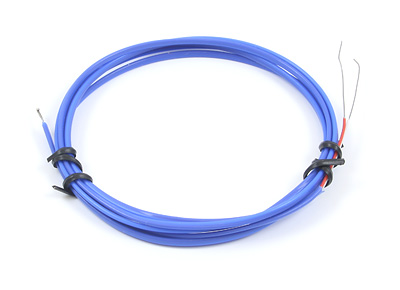
A thermocouple is a device consisting of 2 different conductors that produce a voltage proportional to a temperature difference between either end of the pair of conductors. There are many types of thermocouples, with varying types of conductors and probe designs.
Most thermocouples produce voltages of less than 50mV so very sensitive electronics are required to interface with them.
Choosing a Thermocouple
Conductor Calibration Types
J, K, E and T-Type thermocouples are the most common types of thermocouples. Each type has a different temperature range and resolution due to the metals used in the conductors.
Calibration Type Temperature Ranges:
| Type | Temperature Range °C | Notes |
| K | -200 to +1250 | The most common sensor, wide range, good in oxidizing atmosphere |
| J | 0 to +750 | More Limited range, main application is with old equipment that cannot accept modern thermocouples |
| T | -200 to +300 | Most Accurate base-metal thermocouple, non-magnetic, popular choice for strong magnetic fields and subzero environments |
| E | -200 to +900 | Well suited to low temperature (cryogenic) use |
The insulation that surrounds the thermocouple is the limiting factor in the true temperature range. For example, a K-type thermocouple insulated with teflon is good up to +200°C. The same thermocouple using Fiberglass is good to 480°C. For short durations the thermocouples can be exposed to higher heat than they are rated for, however, they will degrade if exposed to very high heat for long periods of time.
Using Other Thermocouple Types with Phidgets
You can interface with other thermocouple types using Phidgets Inc. thermocouple interfaces, with some minor calculations:
- First, visit this website and open the conversion table for the desired thermocouple type.
- Take the ambient temperature value measured by the board and use the ones digit to select the column, and the other digits to select the row. Record this thermoelectric voltage value.
- Open your Phidget's thermocouple output in VoltageInput mode and read the Voltage property in your program (see the Phidget22 API for details) in order to get the thermocouple's current thermoelectric voltage value.
- Add the two voltage values from the previous steps and use the table to convert back into temperature.
Junction Type

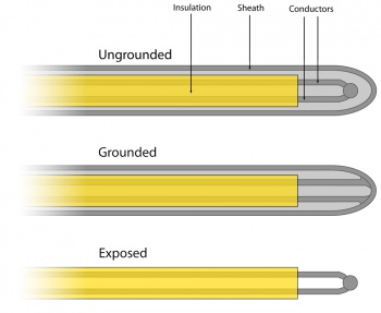
An important feature to consider when choosing a thermocouple is the junction type. This describes the degree to which the sensing end of the thermocouple is exposed to the environment it's measuring. There are three main types of junctions: Grounded, Ungrounded, and Exposed.
Ungrounded
A thermocouple with an ungrounded junction has a metallic outer sheath, usually made of a corrosion-resistant material such as stainless steel. The junction where the two conductors meet is suspended inside this sheath, such that the end of the junction is not in contact with the sheath. As a result, it will take longer for the thermocouple to react to temperature changes in the environment, because the inside of the sheath must reach thermal equilibrium before the conductors can detect the change. Ungrounded thermocouples can be used with a Phidgets Inc. thermocouple interface with no issues as long as the type is also supported.
Advantages:
- The conductors are protected from the environment, enabling the sensor to be used in a wider range of applications.
- Since the conductors are not grounded, the thermocouple will not introduce a ground loop into the system.
Disadvantages:
- It takes longer for the thermocouple to react to temperature changes in the environment because it is not in direct contact with it.
Grounded
A thermocouple with a grounded junction has an outer sheath just like the ungrounded design, but the junction where the two conductors meet is welded to the inside of the sheath. This allows for a shorter reaction time to temperature changes, but is likely to introduce a ground loop into the system. In order to use a grounded thermocouple with a Phidgets Inc. thermocouple interface, should use an isolated thermocouple interface or a USB isolator to ensure system stability.
Advantages:
- The conductors are protected from the environment, enabling the sensor to be used in a wider range of applications.
- Reacts more quickly to temperature changes in the environment.
Disadvantages:
- Special care must be taken to protect your system's stability from ground loops.
Exposed
A thermocouple with an exposed junction has no protective sheath, allowing the junction where the two conductors meet to be in direct contact with the environment it's measuring. As a result, an exposed thermocouple will have the fastest reaction time, but can only be used in non-corrosive, non-pressurized applications (While it is possible to use exposed thermocouples in high pressure applications, it is difficult to make a proper seal. Many enclosed thermocouples will have special hardware for this sort of application). Exposed thermocouples can be used with a Phidgets Inc. thermocouple interface with no issues as long as the type is also supported.
Advantages:
- Exhibits the fastest reaction to temperature changes in the environment due to direct contact.
- Since the conductors are not grounded, the thermocouple will not introduce a ground loop into the system.
Disadvantages:
- Limited to non-corrosive, non-pressurized applications.
- The thermocouple has no protection from physical contact.
Things to Watch For
Grounding

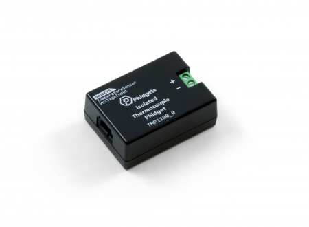
A “ground loop” happens when two points in a circuit are at different potentials, when they are expected to be the same. This difference in electrical potentials causes a build up of static electricity that can give electrical shocks to people and electronics. In the case of thermocouples and non-isolated thermocouple boards, the negative or ground terminal on the board is USB ground. So, if you ground the junction of your thermocouple when using these boards and the material it’s affixed to has a different voltage than the ground on the computer, you’ve created a circuit with two points at different potentials. This problem can be avoided entirely if you use an isolated thermocouple board such as the TMP1100 - Isolated Thermocouple Phidget. More information about how to avoid ground loops in thermocouples can be found here, on the Phidgets blog.
Polarity
Each thermocouple has a positive and a negative lead. If you hook it up with the reverse polarity, you will experience unpredictable readings and incorrect temperatures. Always make sure proper polarity is maintained at each junction and connector along your thermocouple.
Interference
When measuring from a thermocouple, each thermocouple is compared to adapter's internal ground. If your thermocouple is measuring a conductive device which cannot equalize to the ground of the adapter, you should isolate the thermocouple wire using thermally conductive epoxy. Thermocouples are conductive, and are very good at shorting electrical systems together. If in doubt, do not allow the thermocouple wire to contact other metal parts.
Since a thermocouple is essentially just two long wires, it could act like an antenna and pick up electromagnetic interference from other nearby electronics or appliances. See the hardware reliability page for more information on how to deal with this problem.
Wire Size
The maximum temperature varies with the diameter of the wire used in the thermocouple. Although the type of thermocouple dictates the temperature range, the maximum range is also limited by the diameter of the thermocouple wire. That is, a very thin thermocouple may not reach the full temperature range. On the other hand, a thinner thermocouple does reduce the amount of thermal distortion introduced.
Selecting the wire gauge used in the thermocouple sensor depends upon your application. Generally, when longer life is required for the higher temperatures, the larger size gauges should be chosen. When sensitivity is the prime concern, the smaller sizes should be used.
Wire Length
Very long thermocouples are okay (even 100m), but if there are measurement stability issues or USB resets, ferrite beads can be added to the thermocouple wire close to the adapter. See our tutorial on improving hardware reliability for more information.
Note that thermocouples use special wires. This means that if you want to extend the length of your thermocouple you need to use thermocouple wire of the same letter type, not just generic wire. Often, thermocouple extension wire will be rated for a narrower temperature range, since it isn't intended to be used in the sensing end of the application.
Since a thermocouple works due to the interaction at the junction of two different metals, it isn't advisable attach two pieces of thermocouple wire simply by soldering them- This would create an additional junction that would interfere with the measurement signal. The best way to connect two thermocouple wires is to buy a connector of the same letter type that clamps onto either end, such as this K-type connector from Omega.
On the flip side, you can cut thermocouples down to a shorter length if you require that as well. Just make sure to cut the size you want out of the side with the actual sensing area on it. The junction between the 2 metals is what allows the device to measure temperature so you need to have the end with the junction on the length you will be using or the thermocouple won't do anything.
How to connect your Thermocouple
Stripped Wire
Most thermocouples come with the leads just stripped and otherwise unaltered. We recommend a 5 to 6mm wire strip length; the terminal blocks on the majority of adapters will accept wires between 16 - 26 AWG. When using thin wires, make sure that you have a solid connection after tightening the terminal screw.
Connectors
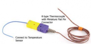
Many K-Type thermocouples are designed to mate with the Subminiature (flat pin) female connector. Listed below are examples of compatible thermocouples from popular sensor manufacturers using this connector.
Compatible Thermocouples:
| Manufacturer | Part Number | Description |
| Omega | TC-PVC-K-24-180 | PVC-insulated 4.5m epoxy-coated tip k-type |
| Omega | 88202K | Moving-surface swivel-head handle k-type |
| Omega | 88402K | Flat-leaf magnetized k-type |
| Nanmac | B8-10 | Handheld trident-style ribbon k-type |
| Cole-Parmer | WU-93631-11 | ICONEL-sheathed high-temp 12” k-type |

