Template:UgVoltageRatioAxis: Difference between revisions
From Phidgets Support
| (2 intermediate revisions by the same user not shown) | |||
| Line 1: | Line 1: | ||
===Voltage Ratio Input (Axis)=== | ===Voltage Ratio Input (Axis)=== | ||
Double click on a Joystick Axis object in order to run the example: | |||
[[Image:{{{1}}}_VoltageRatioSensor_Example.jpg|center|link=]] | |||
{{UGExampleDescription}} | |||
* At the top of the window, information about your device and the properties of this particular channel will be listed. | * At the top of the window, information about your device and the properties of this particular channel will be listed. | ||
* On the left, change trigger and/or data interval can be changed. For more information on these settings, see the [[Data_Rate_and_Change_Trigger|Data Rate/Change Trigger]] page. | * On the left, change trigger and/or data interval can be changed. For more information on these settings, see the [[Data_Rate_and_Change_Trigger|Data Rate/Change Trigger]] page. | ||
| Line 12: | Line 11: | ||
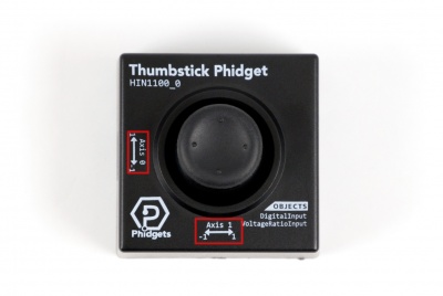
===Joystick Axes=== | ===Joystick Axes=== | ||
Each axis on the joystick is represented as its own VoltageRatioInput object. Axis 0 and Axis 1 are mapped to channels 0 and 1, respectively. You will have to open both channels to fully track the joystick's position. | Each axis on the joystick is represented as its own VoltageRatioInput object. Axis 0 and Axis 1 are mapped to channels 0 and 1, respectively. You will have to open both channels to fully track the joystick's position. | ||
[[File:Joystick_Axes.jpg|center|400px|link=]] | |||
Latest revision as of 17:36, 23 November 2018
Voltage Ratio Input (Axis)
Double click on a Joystick Axis object in order to run the example: [[Image:{{{1}}}_VoltageRatioSensor_Example.jpg|center|link=]]
General information about the selected object will be displayed at the top of the window. You can also experiment with the following functionality:
- At the top of the window, information about your device and the properties of this particular channel will be listed.
- On the left, change trigger and/or data interval can be changed. For more information on these settings, see the Data Rate/Change Trigger page.
- On the right, the voltage ratio is reported in volts per volt. In this case, a value of 1.0 corresponds to the maximum tilt in one direction of the axis, and a value of -1.0 corresponds to the maximum tilt in the other direction. Note: The stick will not be able to fully reach the -1.0 or 1.0 position while inside the enclosure.
Joystick Axes
Each axis on the joystick is represented as its own VoltageRatioInput object. Axis 0 and Axis 1 are mapped to channels 0 and 1, respectively. You will have to open both channels to fully track the joystick's position.

