|
|
| (13 intermediate revisions by 3 users not shown) |
| Line 1: |
Line 1: |
| __NOINDEX__ | | __NOINDEX__ |
| | __NOTOC__ |
| <metadesc>Accurately control the position, velocity, acceleration and current limit of a bipolar stepper motor with the PhidgetStepper Bipolar HC.</metadesc> | | <metadesc>Accurately control the position, velocity, acceleration and current limit of a bipolar stepper motor with the PhidgetStepper Bipolar HC.</metadesc> |
| [[Category:UserGuide]] | | [[Category:UserGuide]] |
| ==Getting Started== | | ==Part 1: Setup== |
| {{UGIntro|1066}} | | <div class="phd-deck-sequence"> |
| *[{{SERVER}}/products.php?product_id=1067 1067 PhidgetStepper HC]
| | {{PT1_1067_CHOOSE}} |
| *USB cable and computer
| | {{PT1_1067_WIN}}{{PT1_1067_MAC}}{{PT1_1067_LNX}} |
| *{{CT|PowerSupply|Power supply}}
| | </div> |
| *{{CT|BipolarStepper|bipolar stepper motor}}
| |
|
| |
|
| | ==Part 2: Using Your Phidget== |
|
| |
|
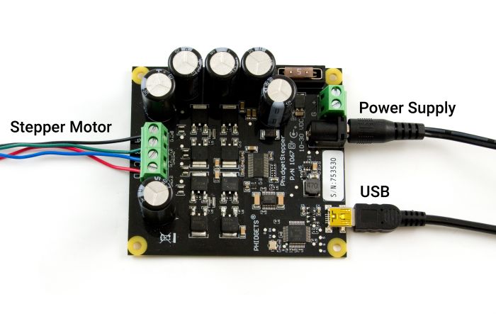
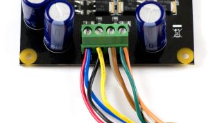
| Next, you will need to connect the pieces:
| | ===Connections Overview=== |
| [[Image:1067_1_Connecting_The_Hardware.jpg|500px|right|link=]]
| |
| # Connect the motor to the PhidgetStepper's input terminal. If you are having difficulty with the wiring, refer to the [[#Technical_Details|technical section]].
| |
| # Push the fuse into the fuse holder beside the power terminals if it isn't already.
| |
| # Connect the power supply to the board using the barrel connector or the power terminal block.
| |
| # Power supplies with higher current (more than 2.5 Amps) should be wired directly to the terminal block.
| |
| # Connect the Phidget to your computer using the USB cable.
| |
|
| |
|
| <br clear="all">
| | [[Image:1067_1_Pinout.jpg|700px|link=]] |
| {{UGIntroDone|1067}}
| |
|
| |
|
| ==Using the 1067==
| | {| |
| {{UGcontrolpanel|1067}} | | | '''USB''' || This device connects directly to your computer, laptop or single-board computer. |
| | |
| {{ugStepperCurrent|1067|PhidgetStepper Bipolar HC}}
| |
| | |
| {{ugAddressingInformation}}
| |
| | |
| {{ugUsingYourOwnProgram| the {{ExampleLink|Stepper}}.}}
| |
| | |
| ==Technical Details==
| |
| ===How does the 1067 control Stepper Motors?===
| |
| The 1067 can be used to control a bipolar stepper motor with 4, 6, or 8 wires.
| |
| | |
| The PhidgetStepper Bipolar is most effective when used with stepper motors designed to be driven with a chopper drive stepper controller. These motors are often large, with a rectangular industrial appearance. The specifications of these motors are often confusing and may seem contradictory. Our users are often confused attempting to relate the specifications of their motor to the capabilities of the 1067. If you are in doubt if your motor will work with the 1067, call us.
| |
| | |
| When the steppers are first engaged from software, the stepper motor likely will not be at the same state as the default output state of the controller. This will cause the stepper to ‘snap’ to the position asserted by the controller - potentially moving by 2 full steps.
| |
| | |
| Unlike the [[1063 User Guide|1063]], the 1067 will always micro-step, moving 1/16th of a step for each change in the position variable.
| |
| | |
| To avoid the use of floating point in the APIs, the position, velocity and acceleration parameters are expressed in microsteps (1/16th steps), instead of full steps. If your application wants to move the motor by 1 full step, you change the position by 16.
| |
| | |
| ====Open and Closed Loop Control====
| |
| Because stepper motors do not have the inherent ability to sense their actual shaft position, they are considered open loop systems.
| |
| | |
| This means that the value contained in the current position property is merely a count of the number of steps that have occurred towards the target value; it can not be relied upon as a measure of the actual shaft angle, as external forces may also be affecting the motor. | |
| | |
| There are several ways of overcoming this drawback. The simplest is to allow the motor load to depress a limit switch located at a known position. This can be used to fire an event in software to recalibrate the shaft position values. A more elegant solution might involve the mounting of an optical encoder on the shaft and the development of a control system.
| |
| | |
| ===How to Connect your Stepper to the 1067===
| |
| | |
| Bipolar Steppers motors are available in 4, 6 or 8 wire configurations. Driving a motor in the Bipolar Configuration produces maximum torque. The word Bipolar means that the controlling electronics have to be able to produce a current flow in either direction in each coil, to produce magnetic fields in opposite directions.
| |
| | |
| ====4 Wire Stepper Motors====
| |
| {{UGbox|
| |
| A 4 wire Stepper motor can only be controlled as a bipolar. There are two coils, with the ends of each coil brought out. By applying current to the two coils in sequence, and changing the direction of current flow, the motor can be made to rotate.
| |
| | |
| Determining how to connect a 4 wire stepper to the 1067 can be done by following this procedure. Suppose we have four wires: red, green, yellow and blue.
| |
| | |
| Start by measuring the resistance between all the wires. Below is a sample table of resistance data, in ohms. This table contains example values, your readings may be different but should still produce a similar pattern.
| |
| |[[File:1063_1_Motor_Types_4wire.jpg|150px|link=]]
| |
| ||}}
| |
| | |
| {| style="border:1px solid darkgray;" cellpadding="7px;" width="40%"
| |
| |-style="background: #e9e9e9" align=center
| |
| ! Wire Color || Green || Blue || Yellow || Red
| |
| |-
| |
| |style="width: 10%; background: #e9e9e9" align=left| '''Green'''
| |
| |style="width: 10%; background: #f0f0f0" align=left|
| |
| |style="width: 10%; background: #F8F8F8" align=left| 30
| |
| |style="width: 10%; background: #F8F8F8" align=left| <font size = 4>∞</font>
| |
| |style="width: 10%; background: #F8F8F8" align=left| <font size = 4>∞</font>
| |
| |- | | |- |
| |style="background: #e9e9e9" align=left| '''Blue'''
| | | '''Power Supply''' || An external power supply is required for this device (10-30VDC). |
| |style="background: #f0f0f0" align=left|
| |
| |style="background: #f0f0f0" align=left|
| |
| |style="background: #F8F8F8" align=left| <font size = 4>∞</font>
| |
| |style="background: #F8F8F8" align=left| <font size = 4>∞</font> | |
| |- | | |- |
| |style="background: #e9e9e9" align=left| '''Yellow'''
| | | '''Stepper Motor''' || Connect a bipolar stepper motor to these inputs. |
| |style="background: #f0f0f0" align=left|
| |
| |style="background: #f0f0f0" align=left|
| |
| |style="background: #f0f0f0" align=left|
| |
| |style="background: #F8F8F8" align=left| 30
| |
| |-
| |
| |style="background: #e9e9e9" align=left| '''Red'''
| |
| |style="background: #f0f0f0" align=left|
| |
| |style="background: #f0f0f0" align=left|
| |
| |style="background: #f0f0f0" align=left|
| |
| |style="background: #f0f0f0" align=left| | |
| |- | | |- |
| | | || |
| |} | | |} |
|
| |
|
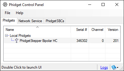
| | ===Phidget Control Panel=== |
|
| |
|
| Looking at the table, you see that there are two pairs of wires (Green-Blue, and Yellow-Red), with roughly the same resistance measured between the wires in each pair. Pick one of the four wires and wire it to the A terminal. The other wire in this pair is connected to the B terminal. At random, wire the other pair to C and D. The motor will turn in clockwise or counter-clockwise rotation. Swapping the A and B wires or the C and D wires will change whether the motor considers “forward” to mean clockwise or counter-clockwise rotation (Remember, steppers can be run in forward or reverse by choosing a target position greater than or less than the current position).
| | Use the Phidget Control Panel to explore your device's functionality. Each channel is described below. |
| | |
| ===6 Wire Stepper Motors===
| |
| {{UGbox|
| |
| In a 6 – wire bipolar motor, there is two + wires, one for each coil, which are the center taps for each coil. You will need to isolate which are the center tap wires and the corresponding wires for their coil.
| |
| | |
| These center taps are left unconnected to operate as a bipolar. Let’s assume our six wire stepper motor wires are colored as follows: red, green, blue, white, purple, and yellow.
| |
| | |
| We measure the resistance between all wires and are presented with the following values in ohms (these are simply example values):
| |
| | |
| |[[File:1062_1_Motor_Types_6wire.jpg|150px|link=]]
| |
| ||}}
| |
| | |
| | |
| {| style="border:1px solid darkgray;" cellpadding="7px;" width="40%"
| |
| |-style="background: #e9e9e9" align=center
| |
| ! Wire Color || Red || White || Yellow || Purple || Green || Blue
| |
| |-
| |
| |style="width: 10%; background: #e9e9e9" align=left| '''Red'''
| |
| |style="width: 10%; background: #f0f0f0" align=left|
| |
| |style="width: 10%; background: #F8F8F8" align=left| <font size = 4>∞</font>
| |
| |style="width: 10%; background: #F8F8F8" align=left| <font size = 4>∞</font>
| |
| |style="width: 10%; background: #F8F8F8" align=left| <font size = 4>∞</font>
| |
| |style="width: 10%; background: #F8F8F8" align=left| 10
| |
| |style="width: 10%; background: #F8F8F8" align=left| 10
| |
| |-
| |
| |style="background: #e9e9e9" align=left| '''White'''
| |
| |style="background: #f0f0f0" align=left|
| |
| |style="background: #f0f0f0" align=left|
| |
| |style="background: #F8F8F8" align=left| 10
| |
| |style="background: #F8F8F8" align=left| 10
| |
| |style="background: #F8F8F8" align=left| <font size = 4>∞</font>
| |
| |style="background: #F8F8F8" align=left| <font size = 4>∞</font>
| |
| |-
| |
| |style="background: #e9e9e9" align=left| '''Yellow'''
| |
| |style="background: #f0f0f0" align=left|
| |
| |style="background: #f0f0f0" align=left|
| |
| |style="background: #f0f0f0" align=left|
| |
| |style="background: #F8F8F8" align=left| 20
| |
| |style="background: #F8F8F8" align=left| <font size = 4>∞</font>
| |
| |style="background: #F8F8F8" align=left| <font size = 4>∞</font>
| |
| |-
| |
| |style="background: #e9e9e9" align=left| '''Purple'''
| |
| |style="background: #f0f0f0" align=left|
| |
| |style="background: #f0f0f0" align=left|
| |
| |style="background: #f0f0f0" align=left|
| |
| |style="background: #f0f0f0" align=left|
| |
| |style="background: #F8F8F8" align=left| <font size = 4>∞</font>
| |
| |style="background: #F8F8F8" align=left| <font size = 4>∞</font>
| |
| |-
| |
| |style="background: #e9e9e9" align=left| '''Green'''
| |
| |style="background: #f0f0f0" align=left|
| |
| |style="background: #f0f0f0" align=left|
| |
| |style="background: #f0f0f0" align=left|
| |
| |style="background: #f0f0f0" align=left|
| |
| |style="background: #f0f0f0" align=left|
| |
| |style="background: #F8F8F8" align=left| 20
| |
| |-
| |
| |style="background: #e9e9e9" align=left| '''Blue'''
| |
| |style="background: #f0f0f0" align=left|
| |
| |style="background: #f0f0f0" align=left|
| |
| |style="background: #f0f0f0" align=left|
| |
| |style="background: #f0f0f0" align=left|
| |
| |style="background: #f0f0f0" align=left|
| |
| |style="background: #f0f0f0" align=left|
| |
| |-
| |
| |}
| |
| Looking at our table, we can see our pattern. The red wire has the same resistance to the green and blue wires. The white wire has the same resistance to the yellow and purple wire. Red, green, and blue are for one pole, and white, yellow, and purple are the other pole. The red and white wires are the center of their coils. Leave the red/white wires unconnected, and follow the instructions for connecting a 4-Wire Bipolar Motor as described earlier in this section.
| |
| | |
| There are in fact two valid combinations, one that will produce a clockwise rotation in the stepper motor for increasing position and one that will produce counter-clockwise rotation. Swapping the A and B wires or the C and D wires will change whether the motor considers “forward” to mean clockwise or counter-clockwise rotation.
| |
| | |
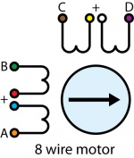
| ====8 Wire Stepper Motors====
| |
| {{UGbox|
| |
| 8 Wire Motors are very difficult to wire up if you do not have a schematic showing how the wires are connected to the internal coils. Only follow these instructions if you are really desperate.
| |
| | |
| In an 8 wire motor, the coils are split, and we have to reconnect the coils, to reduce them to a 4 wire. Assume our eight wire stepper motor wires are colored as follows: red, yellow, purple, orange, blue, green, brown, and white. In an 8-wire stepper motor, these wires would be part of 4 coils, 2 wires per coil. We need to determine the cable pairings.
| |
| | |
| We measure the resistance between each wire and are presented with the following values in ohms (these are simply example values):
| |
| | |
| |[[File:1062_1_Motor_Types_8wire.jpg|150px|left|link=]]
| |
| ||}}
| |
| {| style="border:1px solid darkgray;" cellpadding="7px;" width="40%"
| |
| |-style="background: #e9e9e9" align=center
| |
| ! Wire Color || Orange || Red || Yellow || Purple || Blue || Green || Brown || White
| |
| |-
| |
| |style="width: 10%; background: #e9e9e9" align=left| '''Orange'''
| |
| |style="width: 10%; background: #f0f0f0" align=left|
| |
| |style="width: 10%; background: #F8F8F8" align=left| <font size = 4>∞</font>
| |
| |style="width: 10%; background: #F8F8F8" align=left| <font size = 4>∞</font>
| |
| |style="width: 10%; background: #F8F8F8" align=left| <font size = 4>∞</font>
| |
| |style="width: 10%; background: #F8F8F8" align=left| 1
| |
| |style="width: 10%; background: #F8F8F8" align=left| <font size = 4>∞</font>
| |
| |style="width: 10%; background: #F8F8F8" align=left| <font size = 4>∞</font>
| |
| |style="width: 10%; background: #F8F8F8" align=left| <font size = 4>∞</font>
| |
| |-
| |
| |style="background: #e9e9e9" align=left| '''Red'''
| |
| |style="background: #f0f0f0" align=left|
| |
| |style="background: #f0f0f0" align=left|
| |
| |style="background: #F8F8F8" align=left| <font size = 4>∞</font>
| |
| |style="background: #F8F8F8" align=left| <font size = 4>∞</font>
| |
| |style="background: #F8F8F8" align=left| <font size = 4>∞</font>
| |
| |style="background: #F8F8F8" align=left| 1
| |
| |style="background: #F8F8F8" align=left| <font size = 4>∞</font>
| |
| |style="background: #F8F8F8" align=left| <font size = 4>∞</font>
| |
| |-
| |
| |style="background: #e9e9e9" align=left| '''Yellow'''
| |
| |style="background: #f0f0f0" align=left|
| |
| |style="background: #f0f0f0" align=left|
| |
| |style="background: #f0f0f0" align=left|
| |
| |style="background: #F8F8F8" align=left| <font size = 4>∞</font>
| |
| |style="background: #F8F8F8" align=left| <font size = 4>∞</font>
| |
| |style="background: #F8F8F8" align=left| <font size = 4>∞</font>
| |
| |style="background: #F8F8F8" align=left| 1
| |
| |style="background: #F8F8F8" align=left| <font size = 4>∞</font>
| |
| |-
| |
| |style="background: #e9e9e9" align=left| '''Purple'''
| |
| |style="background: #f0f0f0" align=left|
| |
| |style="background: #f0f0f0" align=left|
| |
| |style="background: #f0f0f0" align=left|
| |
| |style="background: #f0f0f0" align=left|
| |
| |style="background: #F8F8F8" align=left| <font size = 4>∞</font>
| |
| |style="background: #F8F8F8" align=left| <font size = 4>∞</font>
| |
| |style="background: #F8F8F8" align=left| <font size = 4>∞</font>
| |
| |style="background: #F8F8F8" align=left| 1
| |
| |-
| |
| |style="background: #e9e9e9" align=left| '''Blue'''
| |
| |style="background: #f0f0f0" align=left|
| |
| |style="background: #f0f0f0" align=left|
| |
| |style="background: #f0f0f0" align=left|
| |
| |style="background: #f0f0f0" align=left|
| |
| |style="background: #f0f0f0" align=left|
| |
| |style="background: #F8F8F8" align=left| <font size = 4>∞</font>
| |
| |style="background: #F8F8F8" align=left| <font size = 4>∞</font>
| |
| |style="background: #F8F8F8" align=left| <font size = 4>∞</font>
| |
| |-
| |
| |style="background: #e9e9e9" align=left| '''Green'''
| |
| |style="background: #f0f0f0" align=left|
| |
| |style="background: #f0f0f0" align=left|
| |
| |style="background: #f0f0f0" align=left|
| |
| |style="background: #f0f0f0" align=left|
| |
| |style="background: #f0f0f0" align=left|
| |
| |style="background: #f0f0f0" align=left|
| |
| |style="background: #F8F8F8" align=left| <font size = 4>∞</font>
| |
| |style="background: #F8F8F8" align=left| <font size = 4>∞</font>
| |
| |-
| |
| |style="background: #e9e9e9" align=left| '''Brown'''
| |
| |style="background: #f0f0f0" align=left|
| |
| |style="background: #f0f0f0" align=left|
| |
| |style="background: #f0f0f0" align=left|
| |
| |style="background: #f0f0f0" align=left|
| |
| |style="background: #f0f0f0" align=left|
| |
| |style="background: #f0f0f0" align=left|
| |
| |style="background: #f0f0f0" align=left|
| |
| |style="background: #F8F8F8" align=left| <font size = 4>∞</font>
| |
| |-
| |
| |style="background: #e9e9e9" align=left| '''White'''
| |
| |style="background: #f0f0f0" align=left|
| |
| |style="background: #f0f0f0" align=left|
| |
| |style="background: #f0f0f0" align=left|
| |
| |style="background: #f0f0f0" align=left|
| |
| |style="background: #f0f0f0" align=left|
| |
| |style="background: #f0f0f0" align=left|
| |
| |style="background: #f0f0f0" align=left|
| |
| |style="background: #f0f0f0" align=left|
| |
| |-
| |
| |}
| |
| | |
| | |
| This table tells us which wires are parts of a coil. From the table we can tell that red/green, yellow/brown, purple/white, and orange/blue are the coils.
| |
| We are now left with the following situation; we need to determine the proper orientation of the wires to determine our connections. Of each pair, one of the wires will be assigned to A, B, C, or D, and the other wire will be connected to another pair. The number of combinations to be tried to see if they produce rotation is large, but can be reduced to a maximum of 96 possibilities by following these steps:
| |
| # Choose one wire from a pair to connect to A. (2 possibilities)
| |
| # Choose one wire of the other pairs (6 possibilities) and connect to B. The other wire from this pair is connected to the wire from Step 1 not connected to A.
| |
| # Choose one wire from the two remaining pairs (4 possibilities) and connect to C.
| |
| # Choose one wire from the remaining pair (2 possibilities) and connect to the wire from Step 3 not connected to C. The remaining wire from this pair is connected to D.
| |
| # After trying each permutation, engage the motor from software and try to rotate it. Do not connect the pairs to anything - as if you were using a 6-wire stepper in bipolar mode.
| |
| If you attempt to use this algorithm, build a table of permutations beforehand and proceed in a systematic way.
| |
| | |
| There are a total of 96 wiring combinations, of which there are 2 valid combinations where one will cause a clockwise motor rotation and the other will cause a counter-clockwise rotation.
| |
| | |
| If you are not using a Phidget stepper, we suggest consulting any manuals or data sheets that are associated with your particular motor in order to determine the proper wiring for your motor.
| |
| | |
| ===Rescale Factor===
| |
| | |
| {{#ev:youtube|l0n9P9SmNVA}}
| |
| | |
| ===Choosing a Power Supply Voltage===
| |
| | |
| The 1067 can operate from 10 to 30 VDC. It is able to reduce the voltage during operation if your motor requires less, but it cannot increase the voltage. First, find the resistance of the coils in your motor. We will assume 4 Ohms. Add 0.5 Ohms to this to account for the electronics on the 1067. Decide the maximum current you want to push through the coils.
| |
| | |
| This current limit is per coil, and you set this through the software API when you write your application. The maximum current for your stepper is part of the motor specification - you can use the stepper with less current, to reduce power consumption, but you will get reduced torque. We'll assume the limit for this example is 2 Amps. Multiply 4.5 Ohms * 2 Amps = 9 Volts. The minimum voltage you can operate this motor at will be 9 Volts + 0.5 Volts for the controller. If the voltage you provide is less than what is required for the motor (but still more than 9 volts), the motor will still run, but not at full spec, and may not step as smoothly as it could.
| |
| | |
| For more information about how supply voltage affects your motor's maximum speed and torque, check the [[Stepper Motor and Controller Primer#Controlling the Stepper Motor|Stepper Motor Primer]].
| |
| | |
| ===Setting Current Limit===
| |
| | |
| The 1067 allows the current applied to the motor to be programmatically set. This is important - if the current limit is set too high, the motor’s internal resistance will cause the sine-wave approximations used to implement microstepping to clip at the maximum current possible, given your motor/supply voltage. This clipping will cause rough operation, or prevent the motor from turning. If the limit is set too low, the motor may not be able to handle it’s load, by missing steps, or not turning at all at high accelerations.
| |
| | |
| [[File:1063_1_Current_Limiting.jpg|600px|link=]]
| |
| | |
| For more information about setting the current limit, check the [[Stepper Motor and Controller Primer#Controlling the Stepper Motor|Stepper Motor Primer]].
| |
| | |
| ===Continuous Rotation ===
| |
| | |
| A stepper motor can be caused to rotate continuously by simply setting the motor position property to an extremely large number of steps. The valid range of values for the motor position property is large enough to be able to cause the motor to continuously turn at maximum velocity for several years. You could also reset the current position variable whenever the motor reaches a certain position. If the target position is kept the same, this will also produce continuous rotation.
| |
| | |
| ===Saving Power===
| |
| Holding torque is the amount of torque required to rotate the motor ‘against it’s will’ when the full rated current is flowing through the coils. If current consumption / heating is a problem, and full holding torque is not required, the Current Limit can be decreased in software when the motor is not moving. Holding torque will decrease linearly with the Current Limit.
| |
| | |
| There is also a small resistance to movement within the motor even when there is no current, called Detent Torque. This may be sufficient to prevent rotation in your application, particularly if the stepper has a gearbox on it.
| |
| | |
| If the motor is not supporting a load or is not required to maintain a specific angle, it is recommended to set the Enable property to false. This will allow the motor shaft to rotate freely, but the present angle may be lost if forces on the motor-shaft are greater than can be resisted by the detent torque of the unpowered motor.
| |
|
| |
|
| ===High Precision Applications=== | | [[Image:1067_Panel.jpg|link=|center]] |
|
| |
|
| Stepper motor precision is limited by the manufacturing process used to build them. Errors in the rotor and coils will cause some degree of inaccuracy. In our experience, inexpensive stepper motors will often have positioning errors approaching a half-step. Gearing a stepper motor down with a gearbox will reduce this error proportional to the reduction ratio of the gearbox.
| | {{UGC-Start}} |
|
| |
|
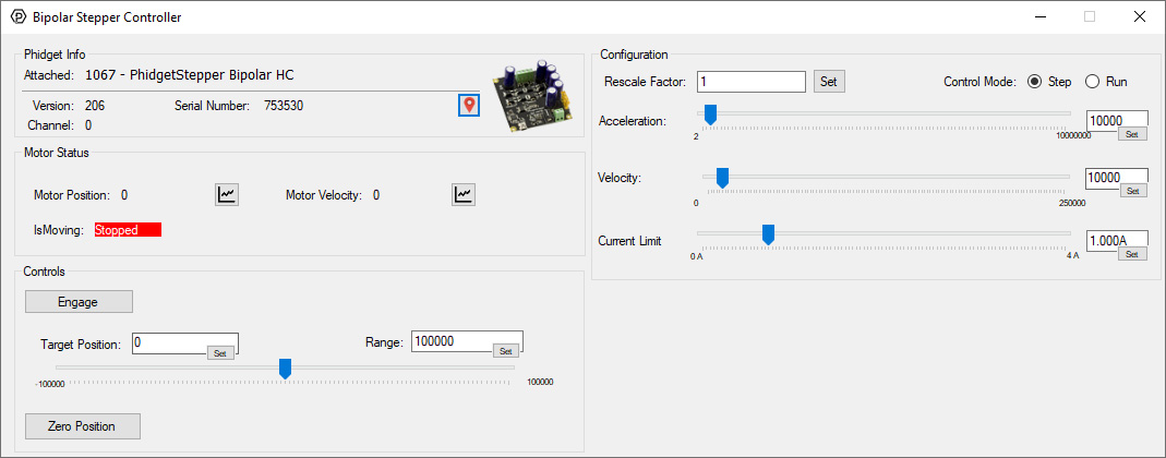
| ===Synchronization of Multiple Motors=== | | {{UGC-Entry|Bipolar Stepper Controller HC || |
| Many applications call for several steppers motors operating in unison - for example, operating a CNC table, or a robot arm. Highly precise synchronization of steppers using the PhidgetStepper is not possible, as the sequencing will be affected by the real-time performance of your operating system. Each stepper is controlled as a independent unit, so there is no way of arranging for a particular action to happen to all motors at the same time. Typical jitter can be 10-30mS.
| | [[Image:1067-Stepper2.jpg|thumb|500px|link=https://cdn.phidgets.com/docs/images/a/a9/1067-Stepper2.jpg|<center>''Stepper Controller application - Phidget Control Panel (Windows)''</center>]] |
| | * This channel allows you to control motor position, speed, current, and more. |
| | * View the [[Stepper API Guide]] for detailed information. |
| | }} |
| | {{UGC-End}} |
|
| |
|
| ===Compatibility Guidelines=== | | ==Part 3: Create your Program== |
| | * [https://www.phidgets.com/?view=code_samples Code Sample Generator] |
| | *[[Programming Resources|Setting up your Programming Environment]] |
| | *[[Phidget Programming Basics]] |
|
| |
|
| When looking for a motor that will be compatible with the 1067, check the motor's data sheet and make sure it meets the following specifications.
| | ==Part 4: Other Considerations== |
| | {{UGC-Start}} |
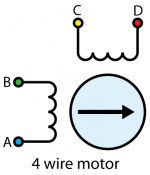
| | {{UGC-Entry|Connecting a 4-Wire Motor|| |
| | [[File:1063_1_Motor_Types_4wire.jpg|150px|right|link=]] |
| | For the motors sold at Phidgets, you can simply wire the motor as follows: |
| | * A - Blue |
| | * B - Red |
| | * C - Black |
| | * D - Green |
|
| |
|
| * '''Bipolar motor''' - While the 1067 can control some six-wire unipolar motors, we recommend you look for bipolar stepper motors.
| | If your motor has an unknown pinout, you can find out which wires share a coil by using a multimeter in resistance or conductivity mode. |
| * '''4, 6, or 8-wire motor''' - A 5-wire motor cannot be used with the 1067, because the coils of the motor are connected internally.
| |
| * '''Rated/Recommended Voltage''' - If the motor comes with a rated or recommended voltage, it should be no more than '''30 volts''', and you should use a power supply that can output that voltage.
| |
| * '''Rated Current''' - The motor should be rated for a maximum of 4A per coil.
| |
|
| |
|
| ===Troubleshooting=== | | If you want the default direction of rotation to be reversed, switch either the A and B or the C and D wires. |
| | }} |
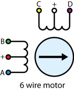
| | {{UGC-Entry|Connecting a 6-Wire Motor|| |
| | [[File:1062_1_Motor_Types_6wire.jpg|150px|right|link=]] |
| | In a 6–wire bipolar motor, there are two + wires, one for each coil, which are the center taps for each coil. You will need to isolate which are the center tap wires and the corresponding wires for their coil. |
|
| |
|
| If your stepper motor is not behaving correctly, you can use a multimeter to determine whether it is the controller or the motor that is at fault.
| | These center taps are left unconnected when using the 1067. Check the datasheet for your motor to find out which wires are the center taps and connect the remaining wires as if it were a 4-wire motor. |
|
| |
|
| Disconnect the motor and set the current limit to 0. Set the target position to 7 and measure the voltage difference between the A and B terminals it should be either -12, or +12V assuming you are using a 12V power supply (just depending on which terminal you have the positive multimeter lead connected to). Then set the target position to 8, the voltage should drop to 0, and it will go to the opposite at 9 (-12 or +12). This pattern will repeat for 39,40,41 and 71,72,73 and 103,104,105 etc... in increments of 32. If this is behaving as expected then the problem is probably with how you have connected your motor, or your code.
| | If you don't know the pinout of your motor, you can use a multimeter to determine which wires belong to the same coil and which ones are the center taps. Use conductivity mode to determine which wires are connected to the same coil. Then, use resistance mode to check the values between each of the wires in the same coil. The center tap is the wire that has a lower resistance between the other wires. |
|
| |
|
| ===Further Reading=== | | }} |
| | {{UGC-Entry|Connecting an 8-Wire Motor|| |
| | [[File:1062_1_Motor_Types_8wire.jpg|150px|right|link=]] |
| | [[File:1067_8wire_Series.jpg|300px|link=|thumb|Series Wiring]][[File:1067_8wire_Parallel.jpg|300px|link=|thumb|Parallel Wiring]] |
| | Check the datasheet for your motor to determine which wires belong the the same coil, and which coils are paired. |
|
| |
|
| For more information about stepper motors, check the [[Stepper Motor and Controller Primer]].
| | 8 Wire Motors are very difficult to wire up if you do not have a schematic showing how the wires are connected to the internal coils. You can use a multimeter to determine which wires pair to the same coil, but you'll need to run the motor trial-and-error to determine which coil pairs with the other. |
|
| |
|
| {{UGnext|}} | | You can wire an 8-wire stepper in series or parallel. Series wiring will result in higher torque when the motor is stopped or at low speeds. Parallel wiring will provide better torque at higher speeds, but less torque overall. Since the current in parallel mode is split between two paths, the current rating is doubled. |
| | }} |
| | {{UGC-Firmware}} |
| | {{UGC-End}} |
