Linear Motion Guide: Difference between revisions
No edit summary |
|||
| (7 intermediate revisions by 2 users not shown) | |||
| Line 1: | Line 1: | ||
{{#seo:|description=Linear systems involve mechanical parts sliding along a track, often driven by ball screws, chain, or belts. Learn the basics about linear motion here.}} | |||
[[Category: | [[Category:IntroGuide]] | ||
==Introduction== | ==Introduction== | ||
The goal of a linear system is to have an object or other subsystem move along a linear track with a controllable velocity and position. The key features of a linear system are the efficiency with which you can move the load, the speed you can move it at, and the accuracy with which you can position the load along the track. Typically a linear system will consist of 1 or more rails/shafts with linear bearings which support the load. The bearing surface is machined to be extremely smooth and is case hardened so it doesn't deform whatsoever under rated load. Then you will also need a drive mechanism so that you can actually control the position along your track. There are a number of options for this such as belt drives, chain drives, and ball screws. Which you use will depend on your specific requirements so lets briefly discuss why and how you would use each. | The goal of a linear system is to have an object or other subsystem move along a linear track with a controllable velocity and position. The key features of a linear system are the efficiency with which you can move the load, the speed you can move it at, and the accuracy with which you can position the load along the track. Typically a linear system will consist of 1 or more rails/shafts with linear bearings which support the load. The bearing surface is machined to be extremely smooth and is case hardened so it doesn't deform whatsoever under rated load. Then you will also need a drive mechanism so that you can actually control the position along your track. There are a number of options for this such as belt drives, chain drives, and ball screws. Which you use will depend on your specific requirements so lets briefly discuss why and how you would use each. | ||
| Line 26: | Line 26: | ||
Note that here we used a belt to drive the ball screw rather than direct drive off the motor. This was just so that we could simplify the chassis. Belt drives allow for more misalignment than shaft couplers do. | Note that here we used a belt to drive the ball screw rather than direct drive off the motor. This was just so that we could simplify the chassis. Belt drives allow for more misalignment than shaft couplers do. | ||
===Belt Drive=== | ===Belt Drive=== | ||
| Line 40: | Line 35: | ||
This style of clamping does reduce the maximum strength of the belt somewhat so you should factor that into your design. Here is an example of a functional single stage belt drive system | This style of clamping does reduce the maximum strength of the belt somewhat so you should factor that into your design. Here is an example of a functional single stage belt drive system | ||
[[image:Belt_drive_assembly_wiki.png|link=|850px|center]] | |||
This is all in reference to linear systems. If you want more information about belt systems in rotary systems you can refer to our [[Rotary Motion Guide]] here. | |||
===Chain Drive=== | ===Chain Drive=== | ||
| Line 57: | Line 49: | ||
[[image:Chain_mount.png|link=|center|700px]] | [[image:Chain_mount.png|link=|center|700px]] | ||
For more information on setting up chain systems you should have a look at our [[Rotary Motion | For more information on setting up chain systems you should have a look at our [[Rotary Motion Guide]] which goes into more depth about the specifics of working with roller chains. | ||
Latest revision as of 19:26, 7 June 2023
Introduction
The goal of a linear system is to have an object or other subsystem move along a linear track with a controllable velocity and position. The key features of a linear system are the efficiency with which you can move the load, the speed you can move it at, and the accuracy with which you can position the load along the track. Typically a linear system will consist of 1 or more rails/shafts with linear bearings which support the load. The bearing surface is machined to be extremely smooth and is case hardened so it doesn't deform whatsoever under rated load. Then you will also need a drive mechanism so that you can actually control the position along your track. There are a number of options for this such as belt drives, chain drives, and ball screws. Which you use will depend on your specific requirements so lets briefly discuss why and how you would use each.
Slides
The first choice is for the type of track you use. The two options available are linear shaft and rail.
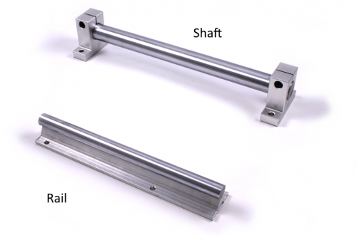
In most cases using rail is preferable. The continuous support under the shaft minimizes deflection under load and it also has many mounting holes along the track which makes for easier and more secure installation in your system. Rail also has the potential for longer travel distances as the shaft won't experience any deflection due to it's own weight. Of course, using rail isn't practical for all applications. In cases where you need to span a gap of some kind or the surface you are travelling along isn't easy to mount to then using suspended shaft is a suitable alternative to rail. There are also flange mount blocks for the shaft so you can mount to a perpendicular surface rather than the pillow blocks shown in the image above.
Drive Systems
There are three main ways to drive your system available from Phidgets:
Ball Screws
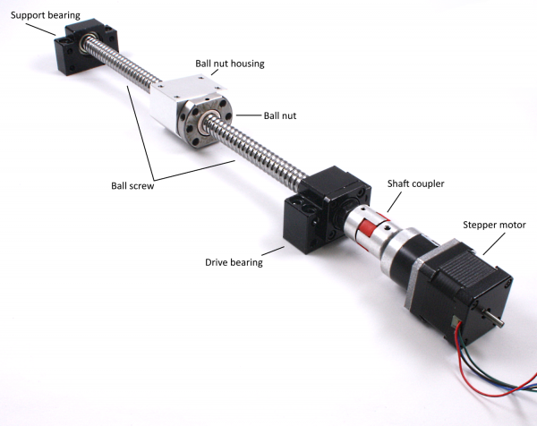
Ball screws allow for very precise positioning with very little backlash. They are also very efficient, meaning they don't require very much force to move a sizeable load in comparison to other methods. A ball screw system typically consists of 4 or 5 elements plus something to turn the screw. To support the screw you need a drive bearing and a support bearing. To apply force to your object you need a nut that will move along the screw (you can also have a housing for the nut depending on how you want to attach your load). Then you of course need the screw itself. Here is an example of a ball screw assembly using a stepper motor to direct drive the screw:
Since the ball screw isn't designed to apply force that is not in the direction of travel we want to use a sliding support system like the rails or shafts mentioned in the slide section. Ideally we should use 2 rails with 1 or more bearings on each. For example:
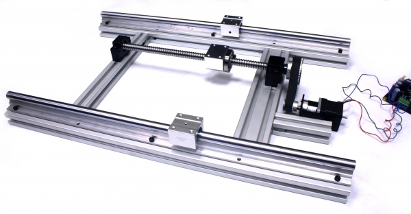
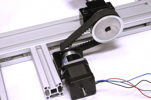
Note that here we used a belt to drive the ball screw rather than direct drive off the motor. This was just so that we could simplify the chassis. Belt drives allow for more misalignment than shaft couplers do.
Belt Drive
A sufficiently tensioned belt will move linearly between the 2 pulleys it is circulating on. We can take advantage of this by attaching something to the belt to have it get pulled along as well. Belt drives are not as precise as ball screws and can have some additional error if there is any slack in the belt. However, they are easier to set up than a ball screw, are more practical for long distance runs, are cheaper, and they can generally move things more quickly.
All you need for a belt drive system is a belt, and 2 pulleys. Similarly to a ball screw system the drive mechanism (your belt) won't be supporting any load other than in the axis of travel. This means that you will need a sliding track made from shaft or rail on which to rest your load. To attach the belt to your load we recommend using some specially designed belt clamps such as the TRM4226 and TRM4227. They can be used to mount a belt to a flat surface on either side for example:
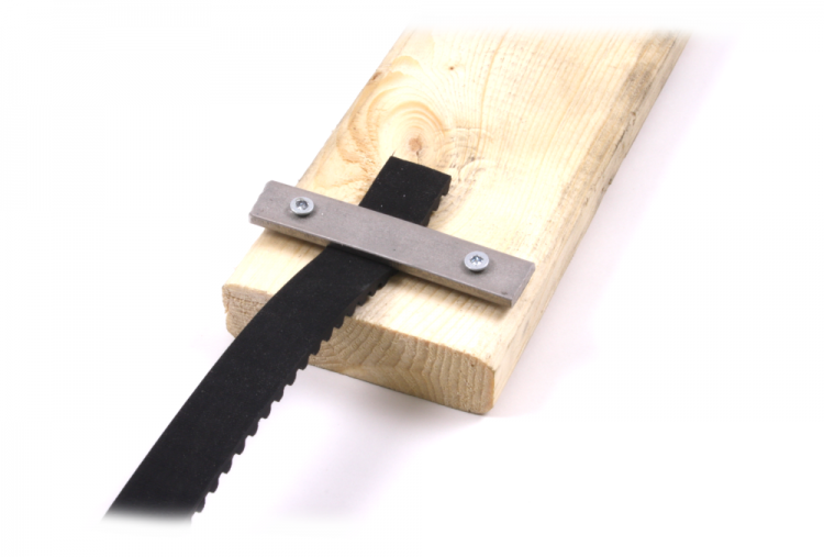
This style of clamping does reduce the maximum strength of the belt somewhat so you should factor that into your design. Here is an example of a functional single stage belt drive system

This is all in reference to linear systems. If you want more information about belt systems in rotary systems you can refer to our Rotary Motion Guide here.
Chain Drive
Chain drives work in an identical fashion to belt drives. They are a bit more complicated to work with but they have the advantage that they can handle much more load than a belt of similar size.
Just replace the pulleys with chain sprockets and the belt with a chain and you are done. Attaching chain to your load is a matter of putting a screw through a hole between chain pitches. For example:
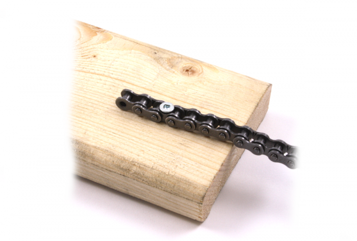
For more information on setting up chain systems you should have a look at our Rotary Motion Guide which goes into more depth about the specifics of working with roller chains.
