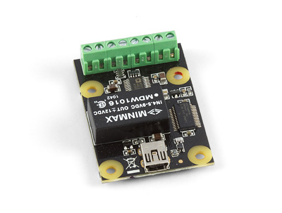
1002 User Guide: Difference between revisions
No edit summary |
No edit summary |
||
| Line 1: | Line 1: | ||
[[Category:UserGuide]] | [[Category:UserGuide]] | ||
{{UserguideTOC|1002.jpg| | {{UserguideTOC|1002.jpg|{{SERVER}}/products.php?product_id=1002}} | ||
==Getting Started== | ==Getting Started== | ||
Revision as of 15:03, 10 August 2012

| |
| Go to this device's product page |
Getting Started
Checking the Contents
|
You should have received:
|
In order to test your new Phidget you will also need:
| |
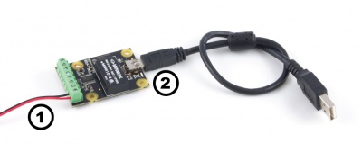
Connecting the Pieces
|
| |
Testing Using Windows 2000 / XP / Vista / 7
Make sure you have the current version of the Phidget library installed on your PC. If you don't, follow these steps:
- Go to the Quick Downloads section on the Windows page
- Download and run the Phidget21 Installer (32-bit, or 64-bit, depending on your system)
- You should see the
 icon on the right hand corner of the Task Bar.
Running Phidgets Sample Program
Double clicking on the ![]() icon loads the Phidget Control Panel; we will use this program to ensure that your new Phidget works properly.
icon loads the Phidget Control Panel; we will use this program to ensure that your new Phidget works properly.
The source code for the Analog-full sample program can be found in the quick downloads section on the C# Language Page. If you'd like to see examples in other languages, you can visit our Languages page.
Updating Device Firmware
If an entry in this list is red, it means the firmware for that device is out of date. Double click on the entry to be given the option of updating the firmware. If you choose not to update the firmware, you can still run the example for that device after refusing.
|
Double click on the |
||
|
Testing Using Mac OS X
- Go to the Quick Downloads section on the macOS page
- Download and run the Phidget macOS Installer
- Click on System Preferences >> Phidgets (under Other) to activate the Preference Pane
- Make sure that the PhidgetAnalog 4-Output is properly attached.
- Double Click on PhidgetAnalog 4-Output in the Phidget Preference Pane to bring up the Analog-full Sample program. This program will function in a similar way as the Windows version.
Using Linux
For a step-by-step guide on getting Phidgets running on Linux, check the Linux page.
Using Windows Mobile / CE 5.0 / CE 6.0
Technical Details
General
Produces a voltage over -10V to +10V. This voltage will be asserted up to +-20mA (short-circuit). An error will be reported when this current is exceeded, and the voltage the customer is getting is no longer accurate. The voltage is produced with 12 bit resolution (4.8mV). The update rate of the outputs is dependant on the speed of your system.
Isolation
The 1002 is not isolated. All 4 channels use the same ground.
Current
The PhidgetAnalog board will limit the available current per channel at approximately 20mA. For reliable results, don’t approach this limit, as it will vary from channel to channel. For maximum accuracy, limit the current to 5mA. If more than +- 20mA of current is drawn, the device goes into a constant current supply mode. When this happens, the current will be held constant at it’s maximum value, and the output voltage will depend on the value of the load that the device is trying to drive.
If your application requires a larger current source / sink, the analog output can be used as an input to a larger external amplifier circuit.
All the power is supplied by the USB bus.
Further Reading
For more information on analog outputs, see the Analog Output Primer.
API
Functions
Template:UGapi Template:UGapi Template:UGapi Template:UGapi Template:UGapi
Events
- ErrorCode = EEPHIDGET_OVERCURRENT
- An overcurrent condition has occured on an output. Under this condition, the output is clamped to 20mA.
- ErrorCode = EEPHIDGET_OVERTEMP
- A Thermal Shutdown state has occured. The outputs will be shut down under this condition.
When overcurrent or overtemperature state have ended, there will be an error event with the EEPHIDGET_OK code. See the ErrorDescription string for specific error details.

