Servo Motor and Controller Guide: Difference between revisions
No edit summary |
No edit summary |
||
| Line 1: | Line 1: | ||
[[Category: Primer]] | [[Category: Primer]] | ||
__TOC__ | __TOC__ | ||
==Introduction== | ==Introduction== | ||
[[Image:1061.jpg|link=|400px|right]] | |||
The broad definition of a servo motor is an automatic device with some sensing mechanism to correct its performance. This primer refers specifically to RC servos. | |||
RC Servos are used for positioning applications. They were originally designed to control remote control (RC) airplanes and their low cost and high torque makes them very useful as an actuator in prototyping applications. An RC Servo can be instructed to move to a desired position by the controller. Internally, it monitors the current position, and drives the motor as fast as it can until it reaches the desired position. This is a very cheap and simple way to control a motor. It has some limitations - there is no way for the controller to know the current position and speed of the motor. Applications that want smooth movement suffer from the aggressive acceleration. | |||
RC Servos are used for positioning applications. They were originally designed to control | |||
==How it Works== | ==How it Works== | ||
A typical servo motor consists of a small [[DC Motor and Controller Primer|DC motor]] driving a gearbox. A [[Potentiometer Primer|potentiometer]] is connected to the output shaft and through the use of some simple electronics, a closed-loop control system is created to monitor and command the motor to move to a specific position. Servos run on a pulse-width modulation (PWM) signal which is a series of square waves where the width of the wave is altered from pulse to pulse. For example: | A typical servo motor consists of a small [[DC Motor and Controller Primer|DC motor]] driving a gearbox. A [[Potentiometer Primer|potentiometer]] is connected to the output shaft and through the use of some simple electronics, a closed-loop control system is created to monitor and command the motor to move to a specific position. Servos run on a pulse-width modulation (PWM) signal which is a series of square waves where the width of the wave is altered from pulse to pulse. For example: | ||
[[File:Servo_PWM.jpg|link=]] | [[File:Servo_PWM.jpg|link=|center]] | ||
The width of each pulse corresponds to a specific rotational position, and different servo motors are mapped differently depending on their range of motion and resolution. For example, the 1 ms pulse in the diagram above might map to a position -45° from the zero position, while the 2 ms pulse might map to the +90° position. This differs slightly from conventional pulse-width modulation because the modulation serves only as an encoded command, and is not used to power the device (The servo motor is powered via the +5V line, not the PWM data line). | The width of each pulse corresponds to a specific rotational position, and different servo motors are mapped differently depending on their range of motion and resolution. For example, the 1 ms pulse in the diagram above might map to a position -45° from the zero position, while the 2 ms pulse might map to the +90° position. This differs slightly from conventional pulse-width modulation because the modulation serves only as an encoded command, and is not used to power the device (The servo motor is powered via the +5V line, not the PWM data line). | ||
| Line 23: | Line 18: | ||
==Choosing a Servo Motor== | ==Choosing a Servo Motor== | ||
[[Image:3000_1.jpg|link=|right|400px]] | |||
Servos have 3 main attributes that must be taken into account when choosing what servo is correct for your application: | Servos have 3 main attributes that must be taken into account when choosing what servo is correct for your application: | ||
| Line 48: | Line 44: | ||
===Digital Servo=== | ===Digital Servo=== | ||
Digital servos behave in the same way as traditional servos except their internals are different. Normally, a servo motor consists of a [[DC Motor and Controller Primer|DC motor]], a [[Potentiometer Primer|potentiometer]], and a small analog circuit which acts as a | Digital servos behave in the same way as traditional servos except their internals are different. Normally, a servo motor consists of a [[DC Motor and Controller Primer|DC motor]], a [[Potentiometer Primer|potentiometer]], and a small analog circuit which acts as a controller to keep the motor in position. In the case of digital servos, the analog circuit is replaced with a microprocessor which performs the same function. This allows digital servos to have faster response times, more accurate control of position and velocity, and more torque per size. However, digital servos use substantially more power than their analog counterparts. This means that for the same power supply you will be able to operate fewer digital servos than analog. Depending on the size of the digital servo, you may need an external power supply when using them with Phidgets Inc. servo controllers. | ||
Some digital servos are designed such that the control system retains its previous value when position commands stop coming in from the controller. This has the unusual effect of making the motor hold its position forcibly even when you disengage the motor programmatically. This can often be undesirable since it means the motor is still drawing power and that it will not turn. In order to avoid this behaviour with this type of servo you will need to use a relay or switch of some kind on the red wire going to the motor (the power wire) so that you can completely disengage the motor when you need to. | Some digital servos are designed such that the control system retains its previous value when position commands stop coming in from the controller. This has the unusual effect of making the motor hold its position forcibly even when you disengage the motor programmatically. This can often be undesirable since it means the motor is still drawing power and that it will not turn. In order to avoid this behaviour with this type of servo you will need to use a relay or switch of some kind on the red wire going to the motor (the power wire) so that you can completely disengage the motor when you need to. | ||
Revision as of 19:46, 6 July 2017
Introduction

The broad definition of a servo motor is an automatic device with some sensing mechanism to correct its performance. This primer refers specifically to RC servos.
RC Servos are used for positioning applications. They were originally designed to control remote control (RC) airplanes and their low cost and high torque makes them very useful as an actuator in prototyping applications. An RC Servo can be instructed to move to a desired position by the controller. Internally, it monitors the current position, and drives the motor as fast as it can until it reaches the desired position. This is a very cheap and simple way to control a motor. It has some limitations - there is no way for the controller to know the current position and speed of the motor. Applications that want smooth movement suffer from the aggressive acceleration.
How it Works
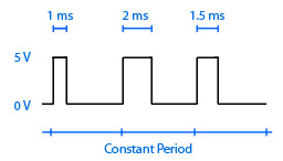
A typical servo motor consists of a small DC motor driving a gearbox. A potentiometer is connected to the output shaft and through the use of some simple electronics, a closed-loop control system is created to monitor and command the motor to move to a specific position. Servos run on a pulse-width modulation (PWM) signal which is a series of square waves where the width of the wave is altered from pulse to pulse. For example:

The width of each pulse corresponds to a specific rotational position, and different servo motors are mapped differently depending on their range of motion and resolution. For example, the 1 ms pulse in the diagram above might map to a position -45° from the zero position, while the 2 ms pulse might map to the +90° position. This differs slightly from conventional pulse-width modulation because the modulation serves only as an encoded command, and is not used to power the device (The servo motor is powered via the +5V line, not the PWM data line).
This is not to be confused with pulse-code modulation, pulse-position modulation, or other types of modulation used to transmit wireless commands to the servo controller. The transmission discussed in this section only refers to the wired communication between the servo controller and servo motors.
Choosing a Servo Motor

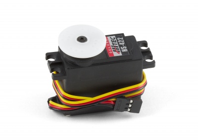
Servos have 3 main attributes that must be taken into account when choosing what servo is correct for your application:
- What range of motion do you need? Servos' range of motion can be shortened programmatically without issue. But to get a larger range, you will need to get a servo that can reach it out of the box. Servos commonly come with 180º range or more.
- How accurate do you need the position control to be? The larger a servo's range of motion is, the less resolution you will have for position accuracy (depending on the quality of the servo).
- How much torque do you need? Some servos provide more torque than others and depending on your application you might need high torque, or low torque.
For more information comparing servo motors with DC motors and stepper motors, see the Motor Selection Guide.
Choosing a Servo Controller
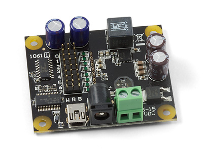
Servo controllers are all generally the same. They have 3 pins per motor, +5V, Ground, and Data. They all produce a PWM (pulse width modulation) signal to control the motors.
The main difference comes in when you need to control multiple motors. Controllers can support different numbers of servos, with the more expensive controllers typically allowing a larger number.
Types of Servo Motors
Servo
The average servo is the most common type of RC (radio control) servo on the market. They work exactly as expected and typically have a range of motion somewhere between 180º and 360º.
Continuous Rotation Servo
These are a subset of servos that do not track position. They have been modified to always report a current position of 0 so when they rotate they keep turning until the target position is set to 0.
Linear Actuator Servo
Linear servos behave like pistons, extending and contracting. This is achieved by using a screw thread at the end of the gearbox, changing the rotational motion to linear motion. Other than that, it behaves the same as any other servo motor.
Digital Servo
Digital servos behave in the same way as traditional servos except their internals are different. Normally, a servo motor consists of a DC motor, a potentiometer, and a small analog circuit which acts as a controller to keep the motor in position. In the case of digital servos, the analog circuit is replaced with a microprocessor which performs the same function. This allows digital servos to have faster response times, more accurate control of position and velocity, and more torque per size. However, digital servos use substantially more power than their analog counterparts. This means that for the same power supply you will be able to operate fewer digital servos than analog. Depending on the size of the digital servo, you may need an external power supply when using them with Phidgets Inc. servo controllers.
Some digital servos are designed such that the control system retains its previous value when position commands stop coming in from the controller. This has the unusual effect of making the motor hold its position forcibly even when you disengage the motor programmatically. This can often be undesirable since it means the motor is still drawing power and that it will not turn. In order to avoid this behaviour with this type of servo you will need to use a relay or switch of some kind on the red wire going to the motor (the power wire) so that you can completely disengage the motor when you need to.
