ENC4109 User Guide: Difference between revisions
From Phidgets Support
No edit summary |
No edit summary |
||
| Line 27: | Line 27: | ||
[[File:ENC4109_Connection1.jpg|400px|link=]] | [[File:ENC4109_Connection1.jpg|400px|link=]] | ||
| | | | ||
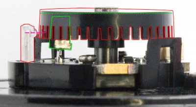
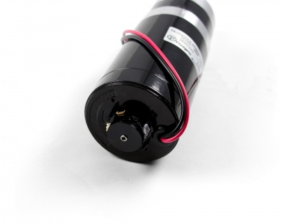
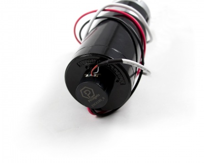
Take the plastic encoder wheel and place it on the shaft with the comb-shaped edge facing the motor. Slowly slide the wheel onto the shaft until the combs are | Take the plastic encoder wheel and place it on the shaft with the comb-shaped edge facing the motor. Slowly slide the wheel onto the shaft until the combs are aligned with the bubble on the optical sensor (Outlined in red below). Be careful not to push so far that the wheel is contacting components on the PCB (outlined in green below). | ||
[[File:ENC4109_Connection2b.jpg|400px|link={{SERVER}}/docs/images/f/f6/ENC4109_Connection2b.jpg]] | |||
| | | | ||
[[File:ENC4109_Connection2.jpg|400px|link=]] | [[File:ENC4109_Connection2.jpg|400px|link=]] | ||
Latest revision as of 20:32, 3 July 2018
Getting Started
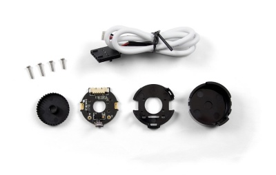
Checking the Contents
|
You should have received:
|
In order to test your new Phidget you will also need:
| |
Connecting the Pieces
|
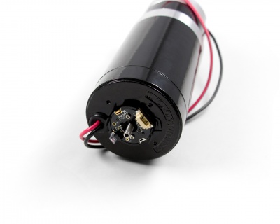
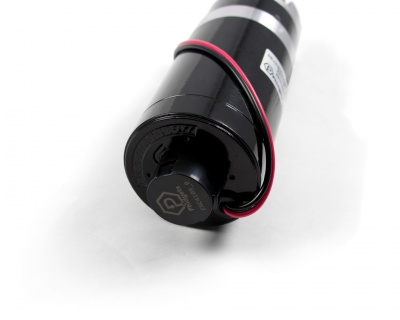
Take the plastic cap and align the hole with the white connector. Press the cap on so that the tabs on either side click in. |
| |
|
Attach the cable to the white connector. You may need to push on either side with your fingernail or a screwdriver to ensure that it's fully inserted. |
| |
|
For further instructions, visit the user guide for the motor controller and encoder interface Phidget that you're using. |
|

