Calibrating Load Cells: Difference between revisions
(Created page with "Analog sensors work by measuring a real world parameter such as temperature, pressure or weight and converting it into an analog voltage that is measurable by your computer....") |
No edit summary |
||
| Line 1: | Line 1: | ||
At the most basic level, load cells measure a real world force by converting it into an analog voltage measurable by a Phidget. Once the Phidget has measured the voltage and sent it to your computer, you can convert it back to units you can work with (e.g. N, kg, lbs). This conversion is made easy due to the face that load cells are designed to output a signal that is directly proportional to the force applied. Apply twice as much force, get twice as much signal. | |||
However, due to manufacturing variations, load cells are fairly unique in the Phidgets product line as sensors that will require individual calibration to get meaningful results in an end application. Thankfully this process is relatively simple, as we will show here. | |||
==How to Calibrate a Load Cell== | |||
For most applications, load cells can be characterized simply in terms of a zero-level offset, and a conversion factor. The zero-level offset being the amount of signal the sensor produces under "no load" conditions, and the conversion factor representing how much the output signal changes for a given change in force. In this context "no load" is understood to mean the amount of force the sensor will see when the system is at rest. | |||
To demonstrate the process of calibrating a load cell, I will use the KIT4007 weigh-scale, with a load cell rated for a maximum weight of 5kg. You should always fully install the sensor in whichever system or application you intend to use it in before calibrating, just in case certain aspects of the construction have an effect on the measurements. | |||
[[Image:KIT4007.jpg|link=|375px]] | |||
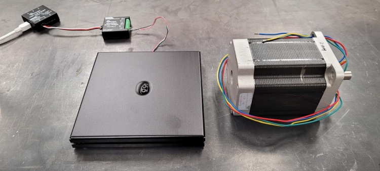
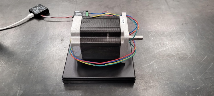
To begin calibration, we will take two measurements: one with the scale empty, and one with a known weight. Depending on the desired accuracy of your system, finding a known weight can be as simple as weighing an object on a trusted scale, and recording the weight. Here I've used a stepper motor which was weighed to be 3.5309kg. | |||
: | |||
[[Image:Reference_Stepper_Weight.png|link=|750px|center]] | |||
[[Image:Reference_Weight_On_Scale.png|link=|750px|center]] | |||
For this example, we used the Phidget Control Panel example to manually read off the load cell readings. | |||
{| | {| | ||
!Weight (kg)!!Reading (V/V) | |||
|- | |||
|0.00 || 4.348e-5 | |||
|- | |||
|3.3509 || 7.55e-4 | |||
|} | |} | ||
To calculate the load cell conversion factor (we'll call it '''M<sub>cal</sub>'''), simply divide the change in weight by the change in sensor reading. | |||
:< | [[Image:LoadCellCalibrationEquation.png|link=|750px|center]] | ||
where '''R<sub>0</sub>''' and '''R<sub>1</sub>''' are the weights used, and '''F<sub>0</sub>''' and '''F<sub>1</sub>''' are the corresponding sensor readings. | |||
</ | |||
Finally, to use your new-found calibration factors you can plug in new sensor readings into the formula: | |||
[[Image:LoadCellEquation.png|link=|750px|center]] | |||
where '''R<sub>0</sub>''' is the zero reference measurement, '''R''' is the latest reading, and '''F''' is the corresponding calibrated weight (in kilograms, for this example). | |||
Revision as of 19:39, 18 November 2021
At the most basic level, load cells measure a real world force by converting it into an analog voltage measurable by a Phidget. Once the Phidget has measured the voltage and sent it to your computer, you can convert it back to units you can work with (e.g. N, kg, lbs). This conversion is made easy due to the face that load cells are designed to output a signal that is directly proportional to the force applied. Apply twice as much force, get twice as much signal.
However, due to manufacturing variations, load cells are fairly unique in the Phidgets product line as sensors that will require individual calibration to get meaningful results in an end application. Thankfully this process is relatively simple, as we will show here.
How to Calibrate a Load Cell
For most applications, load cells can be characterized simply in terms of a zero-level offset, and a conversion factor. The zero-level offset being the amount of signal the sensor produces under "no load" conditions, and the conversion factor representing how much the output signal changes for a given change in force. In this context "no load" is understood to mean the amount of force the sensor will see when the system is at rest.
To demonstrate the process of calibrating a load cell, I will use the KIT4007 weigh-scale, with a load cell rated for a maximum weight of 5kg. You should always fully install the sensor in whichever system or application you intend to use it in before calibrating, just in case certain aspects of the construction have an effect on the measurements.
To begin calibration, we will take two measurements: one with the scale empty, and one with a known weight. Depending on the desired accuracy of your system, finding a known weight can be as simple as weighing an object on a trusted scale, and recording the weight. Here I've used a stepper motor which was weighed to be 3.5309kg.


For this example, we used the Phidget Control Panel example to manually read off the load cell readings.
| Weight (kg) | Reading (V/V) |
|---|---|
| 0.00 | 4.348e-5 |
| 3.3509 | 7.55e-4 |
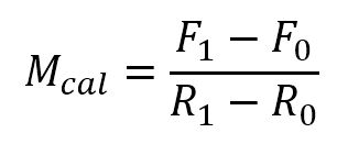
To calculate the load cell conversion factor (we'll call it Mcal), simply divide the change in weight by the change in sensor reading.

where R0 and R1 are the weights used, and F0 and F1 are the corresponding sensor readings.
Finally, to use your new-found calibration factors you can plug in new sensor readings into the formula:

where R0 is the zero reference measurement, R is the latest reading, and F is the corresponding calibrated weight (in kilograms, for this example).
