BLDCMotor API Guide: Difference between revisions
(Created page with "{{#seo:|description=Get started with your Brushless DC Motor Phidget}} Category:IntroGuide <div class="nonumtoc"> <div class="toclimit-4"> =Introduction= thumb|link=https://wwwdev.int.phidgets.com/docs/images/3/38/DCC1120_0.png|<center>30V 50A Brushless DC Motor Phidget (DCC1120_0)</center> This guide will provide information about the Brushless DC Motor (BLDC) API to get you up and running with your new BLDC Motor Phidget. Before starting t...") |
No edit summary |
||
| Line 4: | Line 4: | ||
<div class="toclimit-4"> | <div class="toclimit-4"> | ||
=Introduction= | =Introduction= | ||
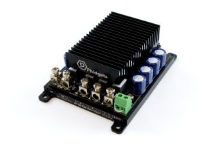
[[Image:DCC1120_0.png|thumb|link=https:// | [[Image:DCC1120_0.png|thumb|link=https://cdn.phidgets.com/docs/images/3/38/DCC1120_0.png|<center>30V 50A Brushless DC Motor Phidget (DCC1120_0)</center>]] | ||
This guide will provide information about the Brushless DC Motor (BLDC) API to get you up and running with your new BLDC Motor Phidget. | This guide will provide information about the Brushless DC Motor (BLDC) API to get you up and running with your new BLDC Motor Phidget. | ||
| Line 16: | Line 16: | ||
|-| | |-| | ||
DCC1120= | DCC1120= | ||
[[Image:DCC1120_0.png|link=https:// | [[Image:DCC1120_0.png|link=https://cdn.phidgets.com/docs/images/3/38/DCC1120_0.png|thumb|200px|[{{SERVER}}/?prodid=1334 30V 50A Brushless DC Motor Phidget (DCC1120_0)]]] | ||
The [ | The [{{SERVER}}/?prodid=1334 30V 50A Brushless DC Motor Phidget (DCC1120_0)] is fully compatible with this guide. | ||
|-| | |-| | ||
DCC1100= | DCC1100= | ||
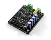
[[Image:DCC1100_0.jpg|link=https:// | [[Image:DCC1100_0.jpg|link=https://cdn.phidgets.com/docs/images/8/87/DCC1100_0.jpg|thumb|200px|[https://www.phidgets.com/?prodid=1013 Brushless DC Motor Phidget (DCC1100_0)]]] | ||
[https://www.phidgets.com/?prodid=1013 Brushless DC Motor Phidget (DCC1100_0)] considerations: | [https://www.phidgets.com/?prodid=1013 Brushless DC Motor Phidget (DCC1100_0)] considerations: | ||
* Stall Velocity is not covered in this guide. Information on this topic is available in the device API. | * Stall Velocity is not covered in this guide. Information on this topic is available in the device API. | ||
| Line 106: | Line 106: | ||
===Braking Strength=== | ===Braking Strength=== | ||
{{ | {{DCMotor_BrakingStrength}} | ||
===Position=== | ===Position=== | ||
| Line 112: | Line 112: | ||
====Other Considerations==== | ====Other Considerations==== | ||
* {{ | * {{DCMotor_RescaleFactorNote}} | ||
* Consider using an encoder for more accurate position information. | * Consider using an encoder for more accurate position information. | ||
Revision as of 19:38, 18 November 2024
Introduction
This guide will provide information about the Brushless DC Motor (BLDC) API to get you up and running with your new BLDC Motor Phidget.
Before starting this guide, visit the Quick Start Guide on your BLDC Motor Phidget's product page for information about wiring and power.
Guide Compatibility
Select your controller for compatibility information relating to this guide.
The 30V 50A Brushless DC Motor Phidget (DCC1120_0) is fully compatible with this guide.
Brushless DC Motor Phidget (DCC1100_0) considerations:
- Stall Velocity is not covered in this guide. Information on this topic is available in the device API.
BLDCMotor API Overview
Phidget Control Panel
After wiring your BLDC Motor Phidget, we recommend opening the Phidget Control Panel on a Windows computer to experiment with key features.
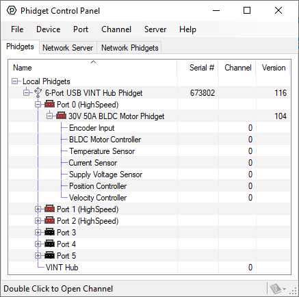
When the BLDC Motor Phidget is powered, it will appear up on the Phidget Control Panel device list as shown above. Double-click on the BLDC Motor Controller entry to view the program.
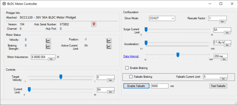
After opening the program, you will see the screen shown above. The program is split into multiple sections to help you get familiar with your motor controller.
- Phidget Info
- Motor Status
- Controls
- Configuration
In this guide, we will focus on the areas that contain important information about controlling your Brushless DC motor. For information about the Phidget Info section, and the Phidget Control Panel in general, visit our Phidget Control Panel Page.
Controls
Without any configuration, you can directly control your motor using the properties in this area of the program.
Target Velocity
This property allows you to control the power being supplied to your motor. At a constant load, increasing the Target Velocity will increase the speed of your motor.
Units of duty cycle are used because the controller uses a pulse-width modulated (PWM) signal to modify the average voltage across your motor.
The table below shows the result of different Target Velocity values when using a 24-volt power supply.
| Velocity | Result |
|---|---|
| 0.0 | The motor is not being powered. The average voltage across your motor is 0V. |
| 1.0 | The motor is fully powered. The average voltage across your motor is 24V. |
| -1.0 | The motor is fully powered (in reverse). The average voltage across your motor is -24V. |
| 0.5 | The average voltage across your motor is 12V. |
| -0.5 | The average volage across your motor is -12V. |
As shown above, Target Velocity does not guarantee a particular velocity in RPM, m/s, etc. (for this, view the Velocity Controller guide). Instead, it allows you to increase motor power, decrease motor power, or reverse the direction of your motor.
Related Parameters
It is important to understand the different parameters that may impact the Target Velocity property:
- When setting a new Target Velocity, the controller will intelligently accelerate (or decelerate) to the new target based on the Acceleration property. This allows for smooth and repeatable movements that improve power consumption.
- The controller can reduce the Velocity if the current through your motor exceeds the Current Limit or Surge Current Limit. This will help keep your system safe in a variety of situations.
- Other conditions such as Over Temperature, Energy Dump, E-Stop, and Failsafe may also impact your Velocity.
Other Considerations
There are two advanced methods of configuring your Phidget that relate to Target Velocity:
Please view the documentation on these topics for more information.
Current Limit
Current limiting is an advanced, yet easy-to-use feature that intelligently monitors and controls the current through your motor. This will help to keep your system safe in a variety of situations.
The datasheet of your motor will specify the following parameters:
- Rated Current
- Stall Current
We recommend setting your Current Limit to 1.1x the rated current of your motor. For increased performance from your motor, review Surge Current Limit.
You may choose to increase the Current Limit significantly above the rated current of your motor. In these situations, it is important to understand how heat will impact your motor.
The heating of your motor increases with the square of the current through your motor. Below is a table showing the approximate time to failure of a 24VDC motor with a 20A rated current and 100A stall current.
| Operating Voltage (VDC) | Operating Current (A) | Heating Rate | Approximate Time to Failure |
|---|---|---|---|
| 24 | 20 | Normal | N/A |
| 24 | 40 | 4x faster than normal | minutes |
| 24 | 100 | 25x faster than normal | seconds |
Many applications rely on a motor operating at higher-than-rated power levels. This is typically done at a low frequency which allows for adequate heat dissipation. Implementing a Surge Current Limit is one way to easily achieve this.
If your controller does not have the Surge Current Limit feature, you may consider dynamically adjusting the Current Limit yourself by monitoring the Current Sensor channel.
Small motors may have a stall current that is less than the minimum Current Limit of your controller. In these situations, your controller will not be able to provide current limiting protection. Consider using a more suitable motor controller or monitor the current yourself via the Current Sensor channel.
Current is directly proportional to torque. If you have an oversized motor that may cause damage to your system downstream, a purposefully reduced Current Limit can provide an extra layer of protection.
Over Temperature conditions may reduce your Current Limit.
Configuration
This area of the program allows you to try out different configurations with your BLDC Motor Phidget to determine the best fit for your application.
Drive Mode
The Drive Mode allows you to configure the deceleration of your motor. There are two modes to choose from:
- Coast Mode (default behavior)
- Forced Mode
Coast Mode
Coast Mode is the default behavior. In this mode, your motor will coast (freewheel) while decelerating. This is similar to the deceleration experienced when releasing the gas pedal in a car.
Other Considerations
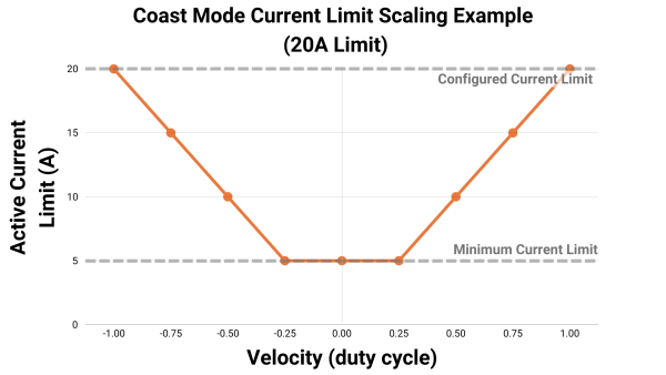
When using Coast Mode your Current Limit will scale based on your motor's Velocity.
The graph below shows the impact of different Velocity values on the Active Current Limit for a 30V 50A Brushless DC Motor Phidget (DCC1120_0).
Notes:
- The minimum Current Limit on the DCC1120_0 is 5A in all situations.
- The Configured Current Limit may refer to a Surge Current Limit if it is set.
Forced Mode
In Forced Mode your motor will aggressively slow down, often regenerating power in the process.
Other Considerations
When using your BLDC Motor Phidget in this mode, you will have full access to your Current Limit.
The table below shows the impact of different Velocity values on the Current Limit for a 30V 50A Brushless DC Motor Phidget (DCC1120_0).
| Drive Mode | Velocity (duty cycle) | Current Limit (A) | Active Current Limit (A) |
|---|---|---|---|
| FORCED | 1.0 | 20 | 20 |
| FORCED | 0.5 | 20 | 20 |
| FORCED | 0.1 | 20 | 20 |
| FORCED | -0.5 | 20 | 20 |
Rescale Factor
The Rescale Factor allows you to change the units of the following properties:
- Position
By default, the units will be in commutations which is dictated by the number of poles/phases your motor and are often non-intuitive. We recommend utilizing the Rescale Factor so your software is easier to understand.
Example Calculations
Generally, most users will prefer units of degrees or rotations. To determine an appropriate Rescale Factor, you will need to know the following values:
- Commutations per revolution, equivalent to the number of poles multiplied by the number of phases
- Gearbox ratio (if applicable)
These values will be available from manufacturer data sheets, or directly on the motor.
Converting to Degrees
Specifications of system:
- Motor gear ratio: 10:1
- Motor poles: 2
- Motor phases: 3
- Preferred Units: Degrees
Rescale Factor = 360 / (10*2*3) = 6
Converting to Rotations
Specifications of system:
- Motor gear ratio: 10:1
- Motor poles: 2
- Motor phases: 3
- Preferred Units: Rotations
Rescale Factor = 1 / (10*2*3) = 0.016666667
Braking Enabled
Braking functionality only applies when the Velocity your controller reports has reached 0.0 (i.e. when your controller is not supplying any power to your motor). Even though no power is supplied at 0.0 duty cycle, your motor may still be turning because of the momentum it built up. Braking can help bring the motor to a stop sooner.
Disabled (Default)
The controller will not attempt to slow down your motor. It will instead allow it to coast (freewheel). When stopped, the shaft will rotate without any increased resistance.
Enabled
When braking has been enabled, the controller will try to forcefully slow down your motor, which will often cause power to flow back to your supply (i.e. regenerative braking). When stopped, your motor will resist rotation with greater resistance.
The controller will intelligently apply brakes, ensuring it abides by the Current Limit and/or Surge Current Limit. To monitor the amount of braking being applied, view the Braking Strength event in your controller's API.
Other Considerations
When Drive Mode is set to Forced, braking is always enabled.
Surge Current Limit
Surge Current Limit is an advanced feature on new Phidget motor controllers. It allows you to safely exceed your Current Limit for a limited time (approximately one second, intelligently determined by your controller), allowing for faster acceleration from your motor than would otherwise be possible.
For applications where faster acceleration is desirable, we recommend setting your Surge Current Limit equal to the stall current of your motor. For all other applications, the Surge Current Limit can be set equal to the Current Limit, which will disable the feature.
Enabling Functionality
| Surge Current Limit vs Current Limit | Surge Current Limit Functionality |
|---|---|
| Surge Current Limit > Current Limit | Enabled |
| Surge Current Limit = Current Limit | Disabled |
| Surge Current Limit < Current Limit | Disabled* |
* The controller ensures that the Surge Current Limit is never set lower than the Current Limit. If an attempt is made to set the Surge Current Limit below the Current Limit, the controller will automatically adjust the Current Limit to match. Similarly, if the Current Limit is set higher than the Surge Current Limit, the controller will increase the Surge Current Limit to match.
Other Considerations
Over Temperature conditions may reduce your Surge Current Limit.
Acceleration
Acceleration directly controls how quickly your controller will adjust its Velocity.
Examples
| Initial Velocity (duty cycle) |
Target Velocity (duty cycle) |
Time to Reach Target Velocity |
|---|---|---|
| 0.0 | 1.0 | 1 second |
| 1.0 | -1.0 | 2 seconds |
| Initial Velocity (duty cycle) |
Target Velocity (duty cycle) |
Time to Reach Target Velocity |
|---|---|---|
| 0.0 | 1.0 | 10 seconds |
| 1.0 | -1.0 | 20 seconds |
| Initial Velocity (duty cycle) |
Target Velocity (duty cycle) |
Time to Reach Target Velocity |
|---|---|---|
| 0.0 | 1.0 | 0.01 seconds |
| 1.0 | -1.0 | 0.02 seconds |
Other Considerations
Increasing your Acceleration will result in faster response times from your motor as shown in the examples above. A high Acceleration will produce larger current swings in your motor when suddenly stopping or changing directions. These swings can be managed by setting an appropriate Current Limit, Surge Current Limit, and by using a Power Guard Phidget.
Data Interval
As with other Phidgets, the Data Interval will change how frequently your controller updates your application with data events. Unless you are implementing a custom control loop, we recommend keeping this at the default for the best performance.
Other Considerations
Using the minimum Data Interval (i.e. the fastest data rate), may impact latency, particularly when running at slower VINT Communication Speeds.
| VINT Communication Speed (kbps) | Data Interval | Latency Impact |
|---|---|---|
| 1000 | Minimum | N/A |
| 100 | Minimum | +2ms |
This increased latency will impact how often you can send commands to your controller.
Motor Status
This area of the program shows information that has been sent back from the BLDC Motor Phidget.
Velocity
The most recent Velocity (duty cycle) value reported by the controller. This value relates to Target Velocity.
Your Target Velocity and Velocity values may differ for the following reasons:
- You set a new Target Velocity, and the controller is intelligently accelerating (or decelerating) to the new target.
- The Current Limit, or another safety feature, has reduced the Velocity to safely control your motor.
Braking Strength
The most recent Braking Strength value reported by the controller. This is directly related to Braking Enabled.
Position
The most recent Position value reported by the controller. The Position is calculated using Hall Effect sensors mounted inside the motor, therefore, the resolution of the position depends on the motor you are using.
Other Considerations
- You can use the Rescale Factor to modify the base units of this property.
- Consider using an encoder for more accurate position information.
Active Current Limit
This value represents the current limit that your controller is actively following. This will often appear as your Surge Current Limit.
You can monitor the Active Current Limit here and the actual current through your motor via the Current Input channel. You'll see that when the Surge Current Limit is exceeded for too long, the Active Current Limit will be reduced.
Motor Inductance
The inductance of a motor is a critical parameter that can significantly improve motor control when understood. The latest generation of Phidget motor controllers automatically measure the inductance of your motor.
You will hear an ascending pair of beeps after the controller has booted indicating the measurement was successful. You will hear no beep, or a descending pair of beeps if the measurement fails.
Other Considerations
- To properly characterize the inductance of your motor, it must be stopped, or turning very slowly when the controller is opened by your application. If this is not possible for your application, consider manually setting the Motor Inductance in the Attach Event. You can use a previously measured value, or a value from your motor's datasheet.
- Inductance measurements will have variations from measurement to measurement, which may cause slight variability in your motor's behavior. If you would like to limit this variability (or you would like to avoid the audible beeps), you can manually set the Motor Inductance in the Attach Event. You can use a previously measured value, or a value from your motor’s datasheet.
- The API for your controller will specify a minimum and maximum Motor Inductance. If your motor falls outside this range, please contact us for more information.
Failsafe
Your controller will enter a Failsafe state in the following circumstances:
- The Failsafe timer has elapsed. For more information, view our Failsafe Guide
- The E-Stop circuit has been opened
When your controller enters a Failsafe state it will apply the Failsafe Settings listed below and reject all communication until the software channel has been closed and reopened.
Failsafe Settings
There are two Failsafe settings that can be customized for your application:
- Failsafe Braking Enabled
- Failsafe Current Limit
Failsafe Braking Enabled
Disabled (Default Behavior)
When disabled (default behavior), your controller will not attempt to slow down your motor upon entering a Failsafe state, it will allow it to coast (freewheel) instead.
Enabled
When enabled, your controller will forcefully slow down your motor upon entering a Failsafe state, which will often cause power to flow back to your supply (i.e. regenerative braking).
Failsafe Current Limit
This will supersede the Current Limit and Surge Current Limit when the controller has entered a Failsafe state.
Other Considerations
The Failsafe timer mentioned above can be enabled or disabled through an API. The E-Stop circuit is always enabled and cannot be disabled. If you do not intend to use it, you must leave the inputs shorted.
E-Stop
New BLDC Motor Phidgets include an E-Stop circuit that can be used to trigger a Failsafe state.
| E-Stop Input Terminals | Result |
|---|---|
| Shorted | Normal operation |
| Open | Failsafe state activated |
The E-Stop input is shorted with a jumper wire by default. If you would like to implement an E-Stop system, we recommend connecting a normally-closed (NC) switch to the E-Stop input.
Other Considerations
The E-Stop circuit does not physically interact with the supply voltage or the motor connection. You should not wire your motor, or your supply voltage to this circuit.
Errors
If the error you are looking for is not mentioned below, please visit the API for your controller.
Energy Dump
New Phidget BLDC Motor controllers include onboard voltage sensing that will attempt to mitigate damage caused by irregular voltage events.
| Input Voltage During Operation (VDC) | Result |
|---|---|
| 8-30 | Normal operation |
| >= 42 | Energy Dump error condition. The BLDC Motor Phidget will attempt to regulate the voltage. The BLDC Motor Phidget will stop controlling the motor, entering a freewheel state until a full power cycle occurs. |
Please note that the voltage regulation mentioned in the table above is not intended to protect against continuous over-voltage conditions and may shorten the life of your controller. To ensure your system is properly protected against these events, a Power Guard Phidget is required.
Over Temperature
New Phidget BLDC Motor controllers include onboard temperature sensing that provides thermal protection for your system. View the table below for more information.
| Temperature | Result |
|---|---|
| < 75°C | Normal operation |
| 75°C to 90°C | Current Limit and Surge Current Limit scaling begins. Your current limits will scale down linearly from your set value as temperature increases, to a maximum of 40A at 90°C. |
| 90°C to 100°C | Current Limit and Surge Current Limit are limited to 40A. |
| >= 100°C | Over Temperature condition. The BLDC Motor Phidget will stop attempting to control the motor. It will enter a freewheel state until the BLDC Motor Phidget is closed and reopened via software. |

