1061 User Guide: Difference between revisions
| Line 145: | Line 145: | ||
* R for Red is 5V | * R for Red is 5V | ||
* W for White (or Yellow depending on your servo motor) is the Data Line | * W for White (or Yellow depending on your servo motor) is the Data Line | ||
If you need to use a servo motor with a higher power requirement than the 1061 can provide, you can cut the red and black wires on the sensor cable and solder them to the power and ground of an external power supply. If you do this, make sure you disconnect the red wire from the 1061, because reverse current from the external power supply could damage the servo controller board. | |||
===Servo Calibration=== | ===Servo Calibration=== | ||
Revision as of 20:31, 29 August 2012
| |
| Go to this device's product page |
Getting Started
Checking the Contents
|
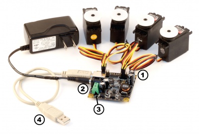
You should have received:
|
In order to test your new Phidget you will also need:
| |
Connecting the Pieces
|
| |
Testing Using Windows 2000 / XP / Vista / 7
Make sure you have the current version of the Phidget library installed on your PC. If you don't, follow these steps:
- Go to the Quick Downloads section on the Windows page
- Download and run the Phidget21 Installer (32-bit, or 64-bit, depending on your system)
- You should see the
 icon on the right hand corner of the Task Bar.
Running Phidgets Sample Program
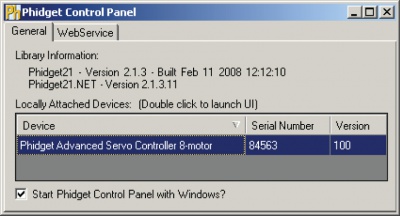
Double clicking on the ![]() icon loads the Phidget Control Panel; we will use this program to ensure that your new Phidget works properly.
icon loads the Phidget Control Panel; we will use this program to ensure that your new Phidget works properly.
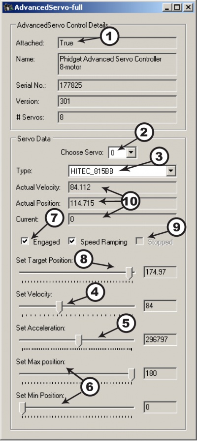
The source code for the AdvancedServo-full sample program can be found in the quick downloads section on the C# Language Page. If you'd like to see examples in other languages, you can visit our Languages page.
Updating Device Firmware
If an entry in this list is red, it means the firmware for that device is out of date. Double click on the entry to be given the option of updating the firmware. If you choose not to update the firmware, you can still run the example for that device after refusing.
|
Double Click on the |
| |
|
|
Testing Using Mac OS X
- Go to the Quick Downloads section on the macOS page
- Download and run the Phidget macOS Installer
- Click on System Preferences >> Phidgets (under Other) to activate the Preference Pane
- Make sure that the Phidget Advanced Servo Controller 8-Motor is properly attached.
- Double Click on Phidget Advanced Servo Controller 8-Motor in the Phidget Preference Pane to bring up the AdvancedServo-full Sample program. This program will function in a similar way as the Windows version.
Using Linux
For a step-by-step guide on getting Phidgets running on Linux, check the Linux page.
Using Windows Mobile / CE 5.0 / CE 6.0
Technical Details
An RC Servo can be instructed to move to a desired position by the controller. Internally, it monitors the current position, and drives the motor as fast as it can until it reaches the desired position. This is a very cheap and simple way to control a motor. It has some limitations - there is no way for the controller to know the current position and speed of the motor. Applications that want smooth movement suffer from the aggressive acceleration.
The PhidgetAdvancedServo is able to address some of these limitations. Instead of sending the desired position immediately, the PhidgetAdvancedServo sends a series of progressive positions according to acceleration and velocity parameters. In most applications, this dramatically smooths the operation of the servo, and allows reasonably precise control of position, velocity and acceleration. The PhidgetAdvancedServo has a built in switching regulator - this allows it to efficiently operate from a wide voltage range (6-15VDC), and maintain proper power to the servo motors even if the power supply is varying. This built in voltage regulator will not operate if your power supply is undersized.
For more information about servo motors and controllers, check out the Servo Motor and Controller Primer.
Current Sense
The PhidgetAdvancedServo continuously measures the current consumed by each motor. The current roughly corresponds to torque, making it possible to detect several scenarios.
- By monitoring for no current, it’s possible to determine if the servo is not connected. It may not be possible to distinguish between a servo at rest and a servo not attached.
- Stalled motors can be detected, by monitoring for the maximum current possible with your motor.
- The position limits of the servo can be programmatically determined by moving the servo until it stalls against the internal or external stops.
Limitations
The PhidgetAdvancedServo does not know the current position of the motor on its own. If your motor is free to move, and is not being driven beyond the physical limitations of the motor, the position returned to your application will be very close to the position of the motor.
Degree Abstraction
The PhidgetAdvancedServo software component uses degrees to specify position, velocity, and acceleration. The degree unit is translated into a pulse sent to the servo, but it’s up to the servo to translate this signal into a particular position. This translation varies between servo models and manufacturers, and it is up to the user to set up their particular servo so that the degree abstraction matches up with reality. Phidgets Inc. has quantified a number of common servo motors (see API section), which can be used with the ServoType function for to set these parameters. For servos not in this list, or to quantify a specific servo, the setServoParameters function can be used.
Defining a Custom Servo
Servos are driven with a PCM (Pulse Code Modulation) signal. To define a custom servo, you need to find the minimum and maximum PCM values that the servo supports.
The easiest way to do this is by bringing up the example and choosing RAW_us_MODE. This will display all positions in microseconds instead of degrees. Move the servo to both of its extremes, stopping when it hits the stops, then easing up a little (leave a few degrees of leaway), and record these values. You could also choose a specific range in degrees that you require and find the PCM values that correspond. Most servos operate within 500us - 2500us.
Record the degrees of rotation that this PCM range represents (using a protractor, for example).
Calculate the maximum velocity of your servo, in degrees/second. Most servos list their max speed in sec/60 degrees. convert this into degrees/second:
The actual maximum velocity of your servo may be slightly higher or lower, as velocity depends on voltage.
Feed these four values into the serServoParameters function to complete the set up. This should be done before any other function are called (in the attach event ideally).
Note that many servos can operate quite a bit outside of their rated ranges.
Degree Abstraction (Historical Model)
Historically, our degree abstraction has been based on the Futaba FP-S148 servo. This is the default abstraction used for the PhidgetAdvancedServo, to maintain backwards compatibility when the new model was added.
Using the 1061 with a Servo Motor
The PhidgetAdvancedServo has been designed to be used with a variety of RC servo motors independent of the motor-specific position, velocity and torque limits. Select a motor that suits your application and falls within the PhidgetAdvancedServo device specifications.
To use a servo motor, first select (in software) which attached motor the PhidgetAdvancedServo should affect. Position, velocity and acceleration can be controlled for each individual motor. The software can also display a readout of the electrical current flowing through each motor.
Using the 1061 with Continuous Rotation Servos
A continuous rotation servo is a servo motor that has had its headgear-stop removed and potentiometer replaced by two matched-value resistors. This has the effect of allowing the motor to rotate freely through a full range of motion, but disables the motor’s ability to control it’s position.
When using the PhidgetAdvancedServo with a servo motor modified in this way, the position control in software becomes the motor’s speed control. Because the two resistors that replace the motor’s potentiometer are matched in value, the motor will always think its shaft is at center position. If the target position in software is set to center, the motor will believe it has achieved the target and will therefore not rotate. The further away from center the target position is set to, the faster the motor will rotate (trying to reach that position, but never doing so). Changing the value above or below center changes the direction of rotation.
Using the 1061 with Electronic Speed Controllers (ESCs)
Electronic Speed Controllers are commonly used in RC hobby planes, cars, helicopters. It’s a controller that accepts a PWM input signal, and controls a motor based on that signal. The ESC accepts power from an external source, normally a battery pack.
ESCs can be controlled by the 1061, but the vast majority of ESCs on the market will destroy the 1061 if they are plugged in without modification. In a hobby RC system, the ESC is responsible for regulating some of the battery current down to ~5V, and supplying it to the radio receiver. An ESC designed to the power the receiver will advertise that it has a Battery Eliminator Circuit (BEC). When you plug an ESC into the 1061, the 1061 is acting as the radio receiver. The 1061 was not designed to be powered by the devices it controls, and the voltage regulator on the 1061 will self-destruct if a device tries to power it. If the center pin from the 3-wire servo connector between the 1061 and the ESC is disconnected, the BEC on the ESC will not be able to power the 1061, and the voltage regulator will not fail.
How the ESC inteprets the PWM signal and controls the motor is a function of the ESC. Higher end ESCs can be configured based on the application.
The hobby RC market has transitioned to Brushless DC Motors (BLDC). As you select an ESC, watch that the battery voltage input matches that of your system, and the type of motor controlled is what you have. Brushed DC and Brushless DC Motors are completely different, and require different controllers.
Wiring layout is critical with ESCs. The currents to the motor and on the ground return can be enormous. If these currents end up travelling back through USB cables, the system will not be stable. Some ESCs are optically isolated (OPTO) - a big advantage that reduces interference.
Connecting your Servo Motor to the 1061
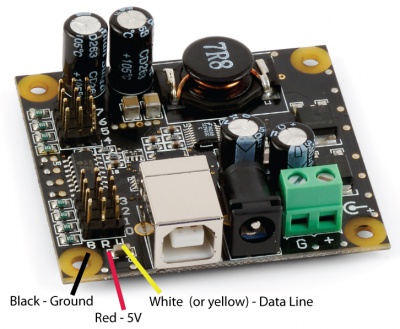
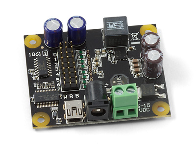
The pins on the 1061 are labelled B R W on the board:
- B for Black is the Ground
- R for Red is 5V
- W for White (or Yellow depending on your servo motor) is the Data Line
If you need to use a servo motor with a higher power requirement than the 1061 can provide, you can cut the red and black wires on the sensor cable and solder them to the power and ground of an external power supply. If you do this, make sure you disconnect the red wire from the 1061, because reverse current from the external power supply could damage the servo controller board.
Servo Calibration
Each servo behaves slightly differently. The Phidgets API provides default calibration parameters that will work with many different models of servo motors; however these values are generic and not specific to each individual unit. It is possible to generate your own values through some manual calibration in the event that your application requires very accurate control or if you are using a servo for which default values are not effective. This is done as follows:
Open the Phidget control panel and open the GUI for the servo controller.
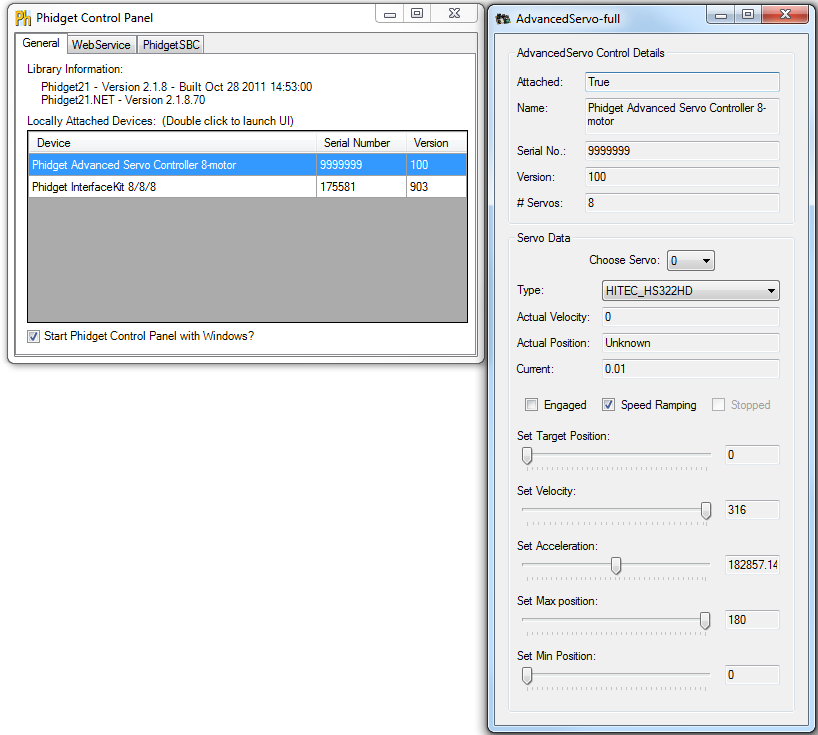
Plug your servo in set the Minimum Pulse Width to ___ and the Maximum Pulse Width to the maximum pulse width limit described in the API for your device.
Set Position at Min and Position at Max to match the Min Pulse Width and Max Pulse Width, respectively. This will allow you to control the actual microsecond pulse width sent to the servo.
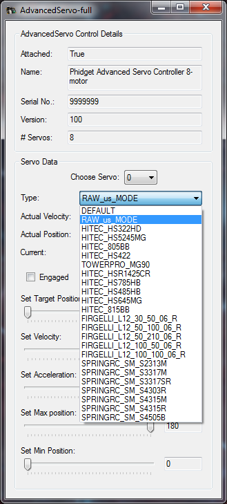
Starting with the target position slider approximately in the middle, engage the motor. The motor should move into position.
Move the target position slider to the left until the motor stops turning. The servo should stop before the slider hits its limit. Take note of the value at which the motor stops, the more precise you can be the better, but the nearest multiple of 10 is usually sufficient. This is the minimum pulse width value and will be used later.
Move the slider to the right and again take note of where the servo stops turning. This will be the maximum pulse width value.
Using a protractor, measure the actual range of movement of the servo motor. This should be close to the rated value but it will likely not match exactly. Accuracy to the nearest degree is good enough.
To do this start with the motor at one extreme. Mark a spot on the motors output shaft in line with 0 degrees and then rotate the motor to its other extreme. Take the value of where the mark you made now rests and that is the motor’s full range of motion. For linear actuators, retract the arm all the way, mark the position of the end of the arm, extend it to its maximum length, and then measure the distance in millimeters from the end of the arm to the old position. In either case, the difference between the positions will correspond to the difference between the Position at Min Pulse Width and the Position at Max Pulse Width.
Finally, check the motor’s data sheet to see the maximum rated velocity. Now that all the measurements have been taken, you can calibrate for the servo.
To test your calibration parameters:
Type your new parameters into their respective boxes in the Motor Calibration box, and type Apply.
Next, set the Velocity slider to the rated velocity of the motor.
The program is now calibrated to the servo motor.
For example:
The HITEC HS-322HD used in testing has the following parameters:
| Argument | Value |
|---|---|
| Min Pulse Width | 540 |
| max_us | 2370 |
| degrees | 180 |
| velocity_max | 316 |
So for example, in C# to initialize the specific HS-322HD tested the following change would be made to the
RCServo example code in the servo_attach function:
        void servo_attach(object sender, AttachEventArgs e)
        {
            ...
            //Set the individual servo parameters
            servo.MinPulseWidth = 540;
            servo.MaxPulseWidth = 2370;
            servo.MinPosition = 0;
            servo.MaxPosition = 180;
            servo.VelocityLimit = 316;
            ...
        }
Your program has now been calibrated to your servo motor. You can get calibration parameters for multiple motors and use all of them in one program should you require it.
API
Data Structures
enum Phidget_ServoType {
- PHIDGET_SERVO_DEFAULT = 1,
- PHIDGET_SERVO_RAW_us_MODE,
- PHIDGET_SERVO_HITEC_HS322HD,
- PHIDGET_SERVO_HITEC_HS5245MG,
- PHIDGET_SERVO_HITEC_805BB,
- PHIDGET_SERVO_HITEC_HS422,
- PHIDGET_SERVO_TOWERPRO_MG90,
- PHIDGET_SERVO_HITEC_HS1425CR,
- PHIDGET_SERVO_HITEC_HS785HB,
- PHIDGET_SERVO_HITEC_HS485HB,
- PHIDGET_SERVO_HITEC_HS645MG,
- PHIDGET_SERVO_HITEC_HS815BB,
- PHIDGET_SERVO_USER_DEFINED
}
Used with the ServoType [get,set] functions. These are servos that have been quantified by Phidget Inc. for your convenience. The Default setting is included for historical reasons, so that the API will be backwards compatible by default. RAW_us_MODE is used for quantifying new servos, or simply when a microsecond based interface makes more sense then a degree based abstraction. USER_DEFINED should never be set directly with ServoType - this is returned when a custom servo type has been defined with setServoParameters.
Functions
Events
Product History
Template:UGhist Template:UGrow Template:UGrow Template:UGrow Template:UGrow

