1057 User Guide: Difference between revisions
(→Events) |
|||
| Line 167: | Line 167: | ||
==Product History== | ==Product History== | ||
{{UGhist}} | {{UGhist}} | ||
{{ | {{UGrow2|1057_0|January 2005 |0|300|Product Release }} | ||
{{ | {{UGrow2|1057_1|November 2009|1|301|Increased pull-up resistance from 1kΩ to 2.2kΩ}} | ||
{{ | {{UGrow2|1057_2|January 2010 |2|302|Replaced USB connector with Mini-USB connector, made board slightly smaller.}} | ||
Revision as of 20:47, 1 April 2014
| |
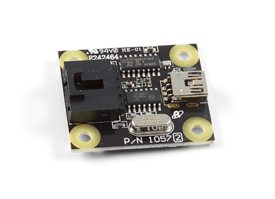
| Go to this device's product page |
Getting Started
Checking the Contents
|
You should have received:
|
In order to test your new Phidget you will also need:
| |
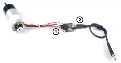
Connecting the Pieces
|
| |
Testing Using Windows 2000 / XP / Vista / 7
Make sure you have the current version of the Phidget library installed on your PC. If you don't, follow these steps:
- Go to the Quick Downloads section on the Windows page
- Download and run the Phidget21 Installer (32-bit, or 64-bit, depending on your system)
- You should see the
 icon on the right hand corner of the Task Bar.
Running Phidgets Sample Program
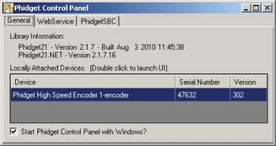
Double clicking on the ![]() icon loads the Phidget Control Panel; we will use this program to ensure that your new Phidget works properly.
icon loads the Phidget Control Panel; we will use this program to ensure that your new Phidget works properly.
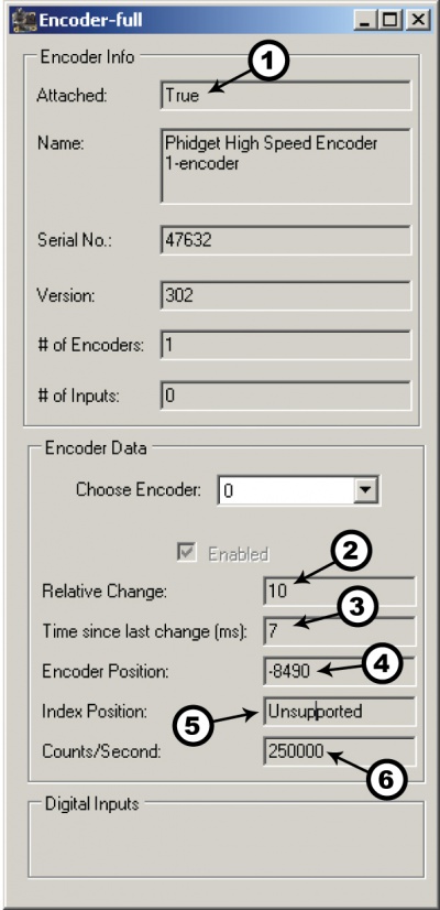
The source code for the Encoder-full sample program can be found in the quick downloads section on the C# Language Page. If you'd like to see examples in other languages, you can visit our Languages page.
Updating Device Firmware
If an entry in this list is red, it means the firmware for that device is out of date. Double click on the entry to be given the option of updating the firmware. If you choose not to update the firmware, you can still run the example for that device after refusing.
|
Double Click on the |
| |
|
|
Testing Using Mac OS X
- Go to the Quick Downloads section on the macOS page
- Download and run the Phidget macOS Installer
- Click on System Preferences >> Phidgets (under Other) to activate the Preference Pane
- Make sure that the Phidget High Speed Encoder is properly attached.
- Double Click on Phidget High Speed Encoder in the Phidget Preference Pane to bring up the Encoder-full Sample program. This program will function in a similar way as the Windows version.
Using Linux
For a step-by-step guide on getting Phidgets running on Linux, check the Linux page.
Using Windows Mobile / CE 5.0 / CE 6.0
Technical Details
The PhidgetEncoder HighSpeed can be used with a wide assortment of mechanical and optical encoders. The encoder should be of quadrature output type, indicating that there will be two output channels (usually labeled A and B). Specifically, the PhidgetEncoder HighSpeed reads a standard incremental non-differential TTL encoder.
The maximum rate of the 1057 PhidgetEncoder is specified at 500,000 cycles per second. In your application, this number relates directly to the number of revolutions per second you wish to measure, and the number of counts per revolution specified for your encoder. If your encoder's wheel has 1000 counts per revolution, then the limit on measurable revolutions per second is 500, or 30,000rpm (which, for the 1057, corresponds to 2000 position changes in software per second).
Choosing Encoders
Both mechanical and optical encoders are available, with optical encoders prevailing in quality at higher revolution speeds. Review the data sheet for the encoder that your are selecting carefully before purchasing it to ensure it is compatible with the PhidgetEncoder HighSpeed. Almost any incremental quadrature encoder will work but it is important to verify this before connecting it to the Phidget. Absolute encoders will not work with this device. Warning: The PhidgetEncoder HighSpeed incorporates a 1kiloOhm pull-up resistor on each line from the encoder input connector. Some encoders will not be able to sink enough current to reliably signal to the 1057. They may work initially, or not at all.
We have reviewed the following encoders, and found that they can be used with the PhidgetEncoder HighSpeed.
This is not meant to be a comprehensive list but should be used as a comparison with other encoders.
| Manufacturer | Web Page | Part Number |
|---|---|---|
| Grayhill | www.Grayhill.com | Series 63R, Series 61R Series 63Q TTL Output |
| US Digital (Recommended) | www.USDigital.com | S4, S5, E2, E3, E4, E4P, etc. |
| Avago Technologies (Formerly Agilent) | www.avagotech.com | HEDS 5500 |
| CUI Inc. | www.cui.com | AMT103-V |
Connectors
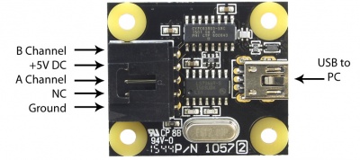
Each Input uses a 3-pin, 0.100 inch pitch locking connector. The connectors are commonly available - refer to the Table below for manufacturer part numbers.
| Manufacturer | Part Number | Description |
|---|---|---|
| Molex | 50-57-9405 | 5 Position Cable Connector |
| Molex | 16-02-0102 | Wire Crimp Insert for Cable Connector |
| Molex | 70543-0004 | 5 Position Vertical PCB Connector |
| Molex | 70553-0004 | 5 Position Right-Angle PCB Connector (Gold) |
| Molex | 70553-0039 | 5 Position Right-Angle PCB Connector (Tin) |
| Molex | 15-91-2055 | 5 Position Right-Angle PCB Connector - Surface Mount |
Note: Most of the above components can be bought at Digikey.
Connector Pinout Diagram
Further Reading
If you want to know more about encoders, check out the Encoder Primer.
API
Functions
Events
C and .NET based APIs only:
Product History
Template:UGhist Template:UGrow2 Template:UGrow2 Template:UGrow2

