ENC4127 User Guide: Difference between revisions
No edit summary |
|||
| Line 18: | Line 18: | ||
'''Step 1:''' Unscrew the encoder cap from the base and separate the pieces. | '''Step 1:''' Unscrew the encoder cap from the base and separate the pieces. | ||
'''Step 2:''' Attach the encoder base to the motor using the two small screws without washers. Make sure the raised edge is facing out so the cap will fit on later. | '''Step 2:''' Attach the encoder base to the motor using the two small screws without washers. Make sure the raised edge is facing out so the cap will fit on later. When tightening the screws, pull the base outward as far as possible, as indicated by the red arrow below. This will ensure there is enough space so the optical reader does not contact the aluminum hub of the encoder wheel. | ||
[[File:ENC4127_Assembly_1-2.jpg|link=]] | [[File:ENC4127_Assembly_1-2.jpg|link=]] | ||
'''Step 3:''' Remove the encoder wheel from the foam packaging and slide it onto the shaft with the | '''Step 3:''' Remove the encoder wheel from the foam packaging and slide it onto the shaft with the aluminum hub facing out. Don't tighten the set screws yet. | ||
'''Step 4:''' Move the optical reader in, sliding the encoder wheel on the shaft so the wheel is resting within the reader's prongs. There are pegs on the bottom of the reader that line up with holes in the base to make this step easier. | '''Step 4:''' Move the optical reader in, sliding the encoder wheel on the shaft so the wheel is resting within the reader's prongs. There are pegs on the bottom of the reader that line up with holes in the base to make this step easier. | ||
| Line 27: | Line 27: | ||
[[File:ENC4127_Assembly_2.jpg|link=|600px]] | [[File:ENC4127_Assembly_2.jpg|link=|600px]] | ||
'''Step 5:''' Once both parts are in place, use the two small screws with washers to mount the reader. Be careful not to overtighten the screws, or you may damage the plastic clips on the reader. | '''Step 5:''' Once both parts are in place, use the two small screws with washers to mount the reader. Be careful not to overtighten the screws, or you may damage the plastic clips on the reader. Ensure that the head of the optical reader does not make contact with the aluminum hub of the encoder wheel. If it does, try loosening the screws of the encoder base and slide it outward. | ||
[[File:ENC4127_Assembly_3.jpg|link=]] | [[File:ENC4127_Assembly_3.jpg|link=]] | ||
'''Step 6:''' Position the encoder wheel so that it is halfway between the reader's prongs, and then tighten both set screws on the wheel's | '''Step 6:''' Position the encoder wheel so that it is halfway between the reader's prongs, and then tighten both set screws on the wheel's aluminum hub using the included allan key. | ||
[[File:ENC4127_Assembly_4.jpg|link=|500px]] | [[File:ENC4127_Assembly_4.jpg|link=|500px]] | ||
Revision as of 15:49, 1 October 2024
Contents
Ensure you have all the pieces before you start assembly:
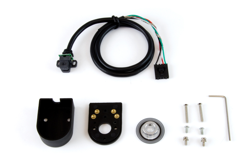
- 2 long screws for enclosure cap
- 2 short screws with washers for the encoder reader
- 2 short screws without washers for the encoder base
- Encoder wheel
- Encoder base and cap
- Allan key for encoder wheel set screws
You'll need a small Phillips head or flathead screwdriver for this assembly.
Assembly Instructions
Step 1: Unscrew the encoder cap from the base and separate the pieces.
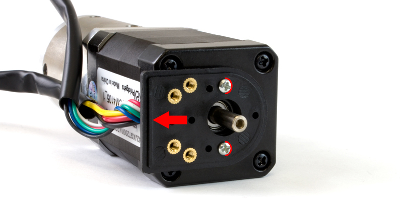
Step 2: Attach the encoder base to the motor using the two small screws without washers. Make sure the raised edge is facing out so the cap will fit on later. When tightening the screws, pull the base outward as far as possible, as indicated by the red arrow below. This will ensure there is enough space so the optical reader does not contact the aluminum hub of the encoder wheel.
Step 3: Remove the encoder wheel from the foam packaging and slide it onto the shaft with the aluminum hub facing out. Don't tighten the set screws yet.
Step 4: Move the optical reader in, sliding the encoder wheel on the shaft so the wheel is resting within the reader's prongs. There are pegs on the bottom of the reader that line up with holes in the base to make this step easier.
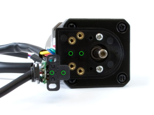
Step 5: Once both parts are in place, use the two small screws with washers to mount the reader. Be careful not to overtighten the screws, or you may damage the plastic clips on the reader. Ensure that the head of the optical reader does not make contact with the aluminum hub of the encoder wheel. If it does, try loosening the screws of the encoder base and slide it outward.
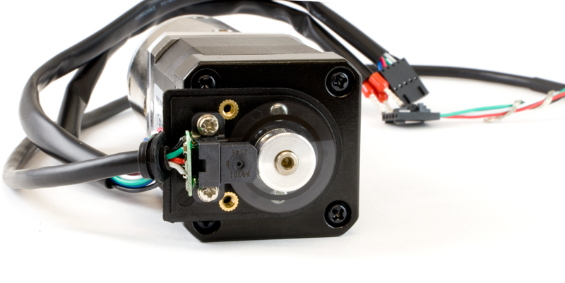
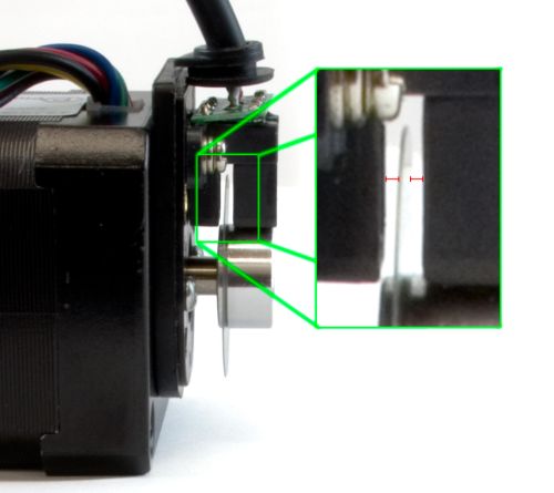
Step 6: Position the encoder wheel so that it is halfway between the reader's prongs, and then tighten both set screws on the wheel's aluminum hub using the included allan key.
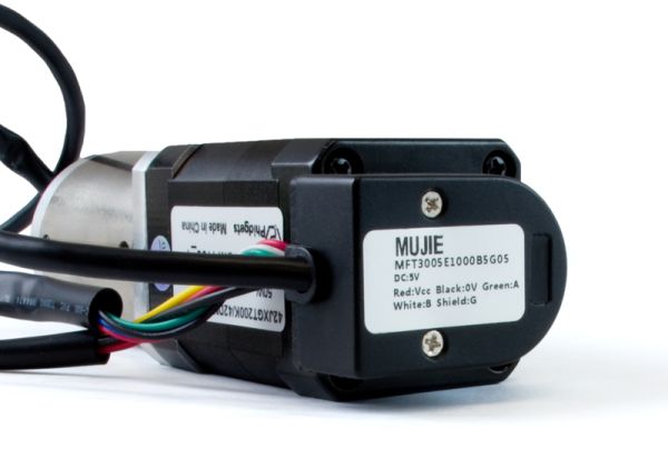
Step 7: Place the cap on the encoder, ensuring that the rubber gasket on the encoder cable is seated in between the base and the cap
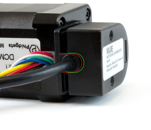
Step 8: Use the two long screws to attach the encoder cap to the base.
