1067 Quick Start Guide
Part 1: Setup
Before you begin using your Phidgets, you will need to install the Phidget Library.
1. Download the installer for your system:
If you're unsure which one you should get, press ⊞ WIN + Pause/Break:
Before installing our libraries, be sure to read our Software License
2. Open the download. If it asks you for permission, select Run and Next
3. Read the Licence Agreement and click Next. Choose the Installation Location and click Next.
Wait for Installation to complete. This should only take a few moments.
Before you begin using your Phidgets, you will need to install the Phidget Library.
- macOS 10.11+: Installer Download
- macOS 10.7 - macOS 10.10:Installer Download
- macOS 10.5 - macOS 10.6:Installer Download
Before installing our libraries, be sure to read our Software License
Open the download and double click on Phidgets.pkg
Select Continue and Read the License and click Agree. Select the installation locationand click Install to continue. MacOS may ask for permission to install. Enter your username and password and Install Software.
You may see a message that the extension has been blocked. Select Open Security Preferences. Beside the message for Phidgets Inc, Click Allow. The installation is now complete.
apt-get install libusb-1.0-0-dev
You’ll also need a C compiler and builder, if you don’t already have one installed.
apt-get install gcc
apt-get install make
Next, download and unpack the Phidgets library:
Use the following commands in the location you unpacked to install the library:
./configure
make
sudo make install
(Optional) You can also download and unpack the following optional packages:
- phidget22networkserver - Phidget Network Server, which
enables the use of Phidgets over your network
- phidget22admin - Admin tool to track who is connected to your
Phidgets when using the network server
- libphidget22extra - Required for phidget22networkserver
and phidget22admin
- libphidget22java - The Java libraries for Phidget22
For installation instructions for these packages, see the README file included with each one.
Part 2: Using Your Phidget
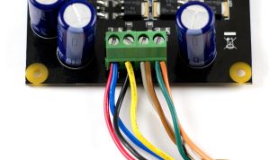
Connections Overview
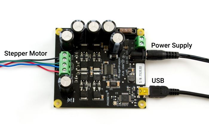
| USB | This device connects directly to your computer, laptop or single-board computer. |
| Power Supply | An external power supply is required for this device (10-30VDC). |
| Stepper Motor | Connect a Stepper motor to these inputs. The typical wiring convention pairs blue with red and green with black, and swapping one of the pairs will reverse the default rotation direction. |
Phidget Control Panel
Use the Phidget Control Panel to explore your device's functionality. Each channel is described below.
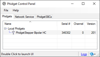
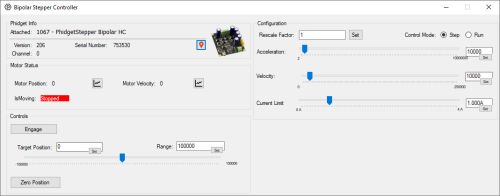
- This channel allows you to control motor position, speed, current, and more.
- View the Stepper API Guide for detailed information.
Part 3: Create your Program
Part 4: Other Considerations
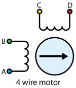
For the motors sold at Phidgets, you can simply wire the motor as follows:
- A - Blue
- B - Red
- C - Black
- D - Green
If your motor has an unknown pinout, you can find out which wires share a coil by using a multimeter in resistance or conductivity mode.
If you want the default direction of rotation to be reversed, switch either the A and B or the C and D wires.
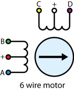
In a 6–wire bipolar motor, there are two + wires, one for each coil, which are the center taps for each coil. You will need to isolate which are the center tap wires and the corresponding wires for their coil.
These center taps are left unconnected when using the 1067. Check the datasheet for your motor to find out which wires are the center taps and connect the remaining wires as if it were a 4-wire motor.
If you don't know the pinout of your motor, you can use a multimeter to determine which wires belong to the same coil and which ones are the center taps. Use conductivity mode to determine which wires are connected to the same coil. Then, use resistance mode to check the values between each of the wires in the same coil. The center tap is the wire that has a lower resistance between the other wires.

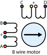
Check the datasheet for your motor to determine which wires belong the the same coil, and which coils are paired.
8 Wire Motors are very difficult to wire up if you do not have a schematic showing how the wires are connected to the internal coils. You can use a multimeter to determine which wires pair to the same coil, but you'll need to run the motor trial-and-error to determine which coil pairs with the other.
You can wire an 8-wire stepper in series or parallel. Series wiring will result in higher torque when the motor is stopped or at low speeds. Parallel wiring will provide better torque at higher speeds, but less torque overall. Since the current in parallel mode is split between two paths, the current rating is doubled.
Before you open a Phidget channel in your program, you can set these properties to specify which channel to open. You can find this information through the Control Panel.
1. Open the Control Panel and double-click on the red map pin icon:

2. The Addressing Information window will open. Here you will find all the information you need to address your Phidget in your program.

See the Phidget22 API for your language to determine exact syntax for each property.
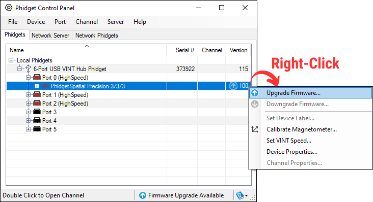
Firmware Upgrade
MacOS users can upgrade device firmware by double-clicking the device row in the Phidget Control Panel.
Linux users can upgrade via the phidget22admin tool (see included readme for instructions).
Windows users can upgrade the firmware for this device using the Phidget Control Panel as shown below.
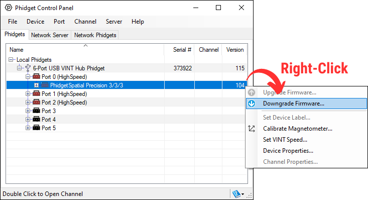
Firmware Downgrade
Firmware upgrades include important bug fixes and performance improvements, but there are some situations where you may want to revert to an old version of the firmware (for instance, when an application you're using is compiled using an older version of phidget22 that doesn't recognize the new firmware).
MacOS and Linux users can downgrade using the phidget22admin tool in the terminal (see included readme for instructions).
Windows users can downgrade directly from the Phidget Control Panel if they have driver version 1.9.20220112 or newer:
Firmware Version Numbering Schema
Phidgets device firmware is represented by a 3-digit number. For firmware patch notes, see the device history section on the Specifications tab on your device's product page.
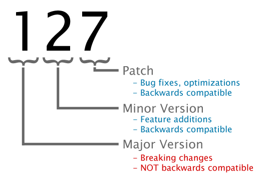
- If the digit in the 'ones' spot changes, it means there have been bug fixes or optimizations. Sometimes these changes can drastically improve the performance of the device, so you should still upgrade whenever possible. These upgrades are backwards compatible, meaning you can still use this Phidget on a computer that has Phidget22 drivers from before this firmware upgrade was released.
- If the digit in the 'tens' spot changes, it means some features were added (e.g. new API commands or events). These upgrades are also backwards compatible, in the sense that computers running old Phidget22 drivers will still be able to use the device, but they will not be able to use any of the new features this version added.
- If the digit in the 'hundreds' spot changes, it means a major change has occurred (e.g. a complete rewrite of the firmware or moving to a new architecture). These changes are not backwards compatible, so if you try to use the upgraded board on a computer with old Phidget22 drivers, it will show up as unsupported in the Control Panel and any applications build using the old libraries won't recognize it either. Sometimes, when a Phidget has a new hardware revision (e.g. 1018_2 -> 1018_3), the firmware version's hundreds digit will change because entirely new firmware was needed (usually because a change in the processor). In this case, older hardware revisions won't be able to be upgraded to the higher version number and instead continue to get bug fixes within the same major revision.
The 1067 allows the current applied to the motor to be programmatically set. This is important - if the current limit is set too high, the motor’s internal resistance will cause the sine-wave approximations used to implement microstepping to clip at the maximum current possible, given your motor/supply voltage. This clipping will cause rough operation, or prevent the motor from turning. If the limit is set too low, the motor may not be able to handle it’s load, by missing steps, or not turning at all at high accelerations.
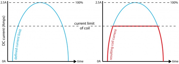
For more information about setting the current limit, check the Stepper Motor Guide.
Stepper motor precision is limited by the manufacturing process used to build them. Errors in the rotor and coils will cause some degree of inaccuracy. In our experience, inexpensive stepper motors will often have positioning errors approaching a half-step. Gearing a stepper motor down with a gearbox will reduce this error proportional to the reduction ratio of the gearbox.