Uncategorized files
Showing below up to 50 results in range #301 to #350.
- 1062 Panel.jpg 411 × 259; 47 KB
- 1062 Stepper Example.jpg 532 × 568; 63 KB
- 1063.jpg 400 × 335; 44 KB
- 1063 1 Connecting The Hardware.jpg 1,303 × 930; 350 KB
- 1063 1 Control Panel Screen.jpg 912 × 481; 209 KB
- 1063 1 Current Limiting.jpg 2,268 × 815; 359 KB
- 1063 1 H Bridge.jpg 716 × 506; 98 KB
- 1063 1 Manager Screen.jpg 948 × 377; 183 KB
- 1063 1 Motor Types.jpg 390 × 1,344; 171 KB
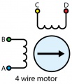
- 1063 1 Motor Types 4wire.jpg 378 × 442; 65 KB
- 1063 1 Motor Types 5wire.jpg 361 × 436; 73 KB
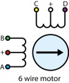
- 1063 1 Motor Types 6wire.jpg 362 × 436; 70 KB
- 1063 1 Motor Types 8wire.jpg 370 × 436; 75 KB
- 1063 1 Stepper screen.jpg 731 × 1,621; 418 KB
- 1063 CurrentInput Example.jpg 461 × 262; 36 KB
- 1063 DigitalInputAL Example.jpg 470 × 240; 27 KB
- 1063 DigitalInput Example.jpg 470 × 240; 27 KB
- 1063 Panel.jpg 505 × 263; 42 KB
- 1063 Stepper Example.jpg 532 × 568; 67 KB
- 1064.jpg 400 × 285; 62 KB
- 1064 0 Testpoints.jpg 927 × 780; 135 KB
- 1064 1 Connecting The Hardware.jpg 901 × 638; 231 KB
- 1064 1 Control Panel Screen.jpg 904 × 479; 202 KB
- 1064 1 MotorControl Screen.jpg 669 × 1,323; 291 KB
- 1064 1 Position Control Diagram.jpg 1,723 × 540; 226 KB
- 1064 1 Testpoints.jpg 781 × 658; 162 KB
- 1064 CurrentInput Example.jpg 461 × 262; 34 KB
- 1064 DCMotor Example.jpg 492 × 552; 59 KB
- 1064 Panel.jpg 505 × 228; 38 KB
- 1065.jpg 400 × 351; 39 KB
- 1065 0 Connecting The Hardware.jpg 1,182 × 896; 395 KB
- 1065 0 Connecting The Hardware Motor.jpg 1,182 × 896; 398 KB
- 1065 0 Connecting The Hardware Motor Sensor.jpg 1,182 × 896; 319 KB
- 1065 0 Connecting The Hardware Potentiometer.jpg 1,092 × 802; 287 KB
- 1065 0 Connecting The Hardware Sensor.jpg 1,130 × 537; 261 KB
- 1065 0 Control Panel Screen.jpg 885 × 527; 212 KB
- 1065 0 Motor Control Screen.jpg 715 × 1,448; 382 KB
- 1065 0 Under.jpg 1,920 × 1,212; 411 KB
- 1065 CurrentInput Example.jpg 461 × 262; 34 KB
- 1065 DCMotor Example.jpg 492 × 552; 60 KB
- 1065 DigitalInputAL Example.jpg 509 × 240; 26 KB
- 1065 DigitalInput Example.jpg 509 × 240; 26 KB
- 1065 Encoder Example.jpg 526 × 347; 59 KB
- 1065 Panel.jpg 505 × 381; 61 KB
- 1065 TestPoints.jpg 708 × 556; 234 KB
- 1065 VoltageInputSensor Example.jpg 558 × 251; 39 KB
- 1065 VoltageInputSupply Example.jpg 572 × 251; 35 KB
- 1065 VoltageRatioSensor Example.jpg 568 × 250; 40 KB
- 1066.jpg 400 × 298; 25 KB
- 1066 0 AdvancedServo Screen.jpg 669 × 1,429; 365 KB


