|
Notice: This page contains information for the legacy Phidget21 Library. Phidget21 is out of support. Bugfixes may be considered on a case by case basis. Phidget21 does not support VINT Phidgets, or new USB Phidgets released after 2020. We maintain a selection of legacy devices for sale that are supported in Phidget21. We recommend that new projects be developed against the Phidget22 Library.
|
Solid State Relay Primer: Difference between revisions
| Line 64: | Line 64: | ||
====DC Voltage (50V or less)==== | ====DC Voltage (50V or less)==== | ||
* for >50V, digikey | * for >50V, digikey | ||
* comes with diode to protect load (diagram) | |||
=====Low Current (6A or less)===== | =====Low Current (6A or less)===== | ||
Revision as of 18:01, 29 November 2011
|
|
Introduction
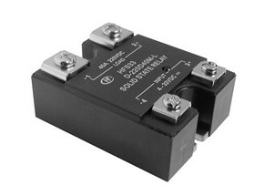
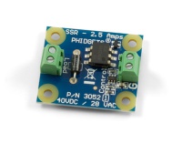
Solid state relays (SSRs) are devices that can be used to turn on or turn off the power being supplied to other devices without the need of a physical switch. With relays, it is possible to control high-current devices with low-current signals, like a standard DC signal from a Digital Output.
Functionally, they are the same as Mechanical Relays, but have the following advantages:
- SSRs produce less electromagnetic interference during operation, as opposed to mechanical relays whose internal contacts tend to spark when switching.
- While the switch contacts of a mechanical relay will eventually wear down from sparking, an SSR will have a longer life because its internals are purely digital.
- SSRs exhibit faster response times than mechanical relays (≈1ms compared to ≈10ms).
- SSRs are less susceptible to electric shock and physical vibrations than mechanical relays.
- Since the switch inside an SSR isn't a mechanical switch, it does not suffer from contact bounce, and operates silently.
Of course, since SSRs are more complex, they are more expensive to produce and will dissipate more energy in the form of heat (1-2% of the energy intended to power the load).
How it Works
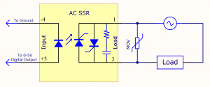
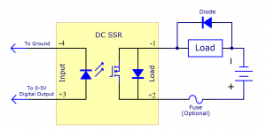
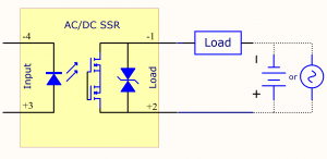
The two inputs are connected internally to an optocoupler. An optocoupler is a circuit component that uses an LED and a light sensitive element to link two parts of a circuit without directly connecting them electrically. The light sensor is connected to the transistors which open and close the path that supplies the relay's load with power.
Basic Use
- talk about basic (and not-so-basic?) uses of relays (switching, dimming?, motor control?)
- talk about switching high power (>20W)
- talk about high-frequency switching (and other max specs)
- list other challenges and solutuons
- why does some current leak through SSR?
- advantage of SSR is long life, but will only achieve this if they avoid overtemp, overcurrent, overvoltage, excessive transients.
- using bigger wires
- Safety related stuff:
Since relays can switch high currents and voltages, they can be potentially quite hazardous. Make sure you never touch the terminals while the relay is powered, and use the plastic cover if the relay came with one. Even when the relay is open, there will still be a small amount of leakage current (≈1-10mA) running through the load.
Also ensure the terminal screws are tightened properly, as loose screws could cause excess heat to be generated.
Choosing an SSR
There many factors to consider when choosing an SSR, and you need to know what kind your application needs before deciding on one.
- how to calculate current based on wattage
What are you trying to Switch?
Mains Voltage (120V or 240V AC)
- Why 240 sold as 120?
On/Off
Dimming
Low Voltage AC (28V AC or less)
Low Current (6A or less)
- AC/DC relays
High Current (greater than 6A)
- ???
DC Voltage (50V or less)
- for >50V, digikey
- comes with diode to protect load (diagram)
Low Current (6A or less)
- AC/DC relays
High Current (greater than 6A)
- hongfa DC relays
- use lower voltage if possible for greater efficiency
Application Load
Be sure to choose an SSR that can handle the current and voltage requirements of the load you're switching. This is often more complicated than making sure the rated currents and voltages match, since some devices can have quick surges of current on startup. As a general rule, make sure the SSR can handle the maximum surge value of your application, not just the usual operating current.
- Talk about transformers
- talk about lamps
- talk about heaters
Do you need a heatsink?
Check your SSR's data sheet to get an idea of the amount of heat it will be generating based on your application's load. If the SSR cannot be mounted on a surface that is suitable for conducting away the heat, you should use a heatsink.
- How to tell if SSR is "too hot"?
- causes of excess heat- too much current or too little heatsinking
Noise Protection
Some AC relays will typically have built-in noise protection in the form of a "snubber". A snubber is a simple RC circuit that will absorb small transients and will protect against unintentional turn-on.
For large transients and highly inductive loads, additional protection is necessary. A simple way to do this is to add a Metal Oxide Varistor (MOV) across the load terminals.
Types of Solid State Relays
The main defining characteristic that separates Solid State Relays (SSRs) is the type of current they can switch. If you want to read about Mechanical Relays instead, you can visit the
Alternating Current (AC)
Zero-cross Turn-on vs. Random Turn-on
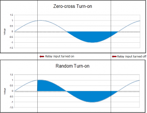
AC SSRs are designed to either have have a zero-cross turn-on or a random turn-on characteristic. The type you should choose is determined by the nature of the load you're switching. If you're switching a DC load, you can ignore this section.
Zero-cross Turn-on
An SSR with this feature will only switch on when the proper voltage is applied to the input terminals and when the output voltage is near zero. This is ideal for applications with resistive loads or systems that want to avoid sharp voltage changes.
The relay will turn off when the input voltage is close to zero and the load current is near zero.
Random Turn-on
An SSR with this feature will immediately switch on when the proper voltage is applied to the input terminals, regardless of what voltage the output terminals are at. This is ideal for applications with inductive loads, since using a zero-cross turn-on SSR with an inductive load could cause the relay to stay on indefinitely.
The relay will turn off when the input voltage is close to zero and the load current is near zero.
Metal Oxide Varistors (MOVs)
- What do they do/When are they needed?
- How to connect an MOV
Direct Current (DC)
Versatile (AC/DC)
- show diagram of AC/DC SSR
Proportional Control
Proportional Control Relays (often simply called "Control Relays") are SSRs that can gradually open or close proportional to the amount of power provided to the input, rather than simply being completely open or completely closed.
Conclusion
- reiterate introduction, quickly review important features and differences of various SSRs
How to Buy
- table of SSRs categorized with product links

