
The 1121 provides an interface to non-Phidgets resistance sensors such as: Force-Sensing Resistors (FSR), light sensors, thermistors (heat sensors), and bend sensors.
The Voltage Divider eliminates the need to connect a resistor to an analog input by providing a high precision potentiometer. You can adjust the resistance by turning the trim pot on the side of the resistor.
This adapter can be used to interface one Interlink FSR. Here's a complete list of all the different varieties we sell:
| Product | Sensor Properties | Physical Properties | ||
|---|---|---|---|---|
| Part Number | Price | Force Min | Force Max | Sensing Area |
 Interlink Electronics 0.2″ Circular 20N FSR
|
$6.50 | 1 N | 20 N | 19.6 mm² |
 Interlink Electronics 0.5″ Circular 20N FSR
|
$7.50 | 1 N | 20 N | 126.7 mm² |
 Interlink Electronics 1.5″ Square 20N FSR
|
$10.00 | 1 N | 20 N | 14.5 cm² |
This adapter can be read by any Phidget with an Analog Input or VINT Hub port. It will connect to either one using the included Phidget cable. VINT Hub ports can behave just like Analog Inputs, but have the added flexibility of being able to be used as digital inputs, digital outputs, or ports to communicate with VINT devices. For more information about VINT, see the VINT Overview page.
| Product | Voltage Inputs | ||
|---|---|---|---|
| Part Number | Price | Number of Voltage Inputs | Voltage Input Resolution (bits) |
 VINT Hub Phidget
|
$40.00 | 6 (Shared) | *** 15 bit |
 1-Port VINT Hub Phidget
|
$24.00 | 1 (Shared) | ** 16 bit |
 VINT Hub Phidget
|
$35.00 | 6 (Shared) | * 15 bit |
 VINT Hub Phidget
|
$30.00 | 6 (Shared) | *** 15 bit |
 Wireless VINT Hub
|
$60.00 | 6 (Shared) | * 16 bit |
 PhidgetSBC4
|
$120.00 | 6 (Shared) | * 16 bit |
 PhidgetInterfaceKit 8/8/8
|
$80.00 | 8 | — |
 PhidgetInterfaceKit 2/2/2
|
$50.00 | 2 | 10 bit |
 8x Voltage Input Phidget
|
$20.00 | 8 | 12 bit |
 PhidgetInterfaceKit 8/8/8
|
$80.00 | 8 | 10 bit |
 PhidgetInterfaceKit 8/8/8 Mini-Format
|
$70.00 | 8 | 10 bit |
 PhidgetInterfaceKit 8/8/8 w/6 Port Hub
|
$110.00 | 8 | 10 bit |
 PhidgetTextLCD 20X2 : White : Integrated PhidgetInterfaceKit 8/8/8
|
$70.00 | 8 | 10 bit |
This adapter comes with its own Phidget cable to connect it to an InterfaceKit or Hub, but if you need extras we have a full list down below. You can solder multiple cables together in order to make even longer Phidget cables, but you should be aware of the effects of having long wires in your system.
| Product | Physical Properties | |
|---|---|---|
| Part Number | Price | Cable Length |
 Phidget Cable 10cm
|
$1.50 | 100 mm |
 Phidget Cable 30cm
|
$1.75 | 300 mm |
 Phidget Cable 60cm
|
$2.00 | 600 mm |
 Phidget Cable 60cm
|
$2.00 | 600 mm |
 Phidget Cable 90cm
|
$2.00 | 900 mm |
 Phidget Cable 120cm
|
$2.25 | 1.2 m |
 Phidget Cable 150cm
|
$2.50 | 1.5 m |
 Phidget Cable 180cm
|
$2.75 | 1.8 m |
 Phidget Cable 350cm
|
$3.00 | 3.5 m |
 Phidget Cable Kit
|
$10.00 | 80 mm |
 Phidget Cable Extension Wire 22AWG
|
$0.75/Meter | — |
Welcome to the 1121 user guide! In order to get started, make sure you have the following hardware on hand:
Next, you will need to connect the pieces:
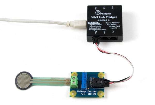
Now that you have everything together, let's start using the 1121!
In order to demonstrate the functionality of the 1121, we will connect it to the HUB0000, and then run an example using the Phidget Control Panel on a Windows machine.
The Phidget Control Panel is available for use on both macOS and Windows machines. If you would like to follow along, first take a look at the getting started guide for your operating system:
Linux users can follow the getting started with Linux guide and continue reading here for more information about the 1121.
After plugging in the 1121 into the HUB0000, and the HUB0000 into your computer, open the Phidget Control Panel. You will see something like this:
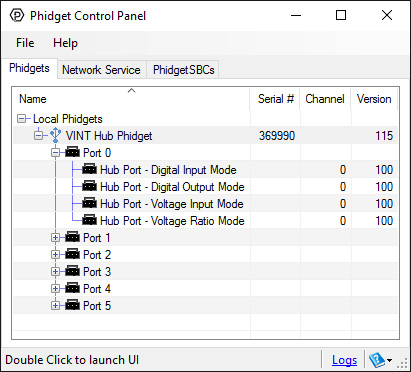
The Phidget Control Panel will list all connected Phidgets and associated objects, as well as the following information:
The Phidget Control Panel can also be used to test your device. Double-clicking on an object will open an example.
Double-click on a Voltage Ratio Input object in order to run the example:
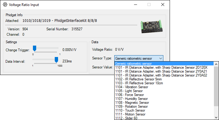
General information about the selected object will be displayed at the top of the window. You can also experiment with the following functionality:
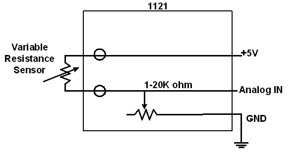
Why is adjusting the resistance important? The Voltage Input can measure a voltage between 0 and 1.0 voltage ratio (i.e. 0V to 5V if you have a 5V supply). When using variable resistance devices a voltage divider is commonly used to measure the changing resistance. The two resistors in the divider form a voltage, based on the ratio between them. This voltage is then measured by the Voltage Input. To optimize the voltage divider to meet your needs, you have to adjust the fixed resistance to match the characteristics of your chosen sensor. To adjust the resistance on the 1121, simply turn the screw on the potentiometer clockwise to decrease the resistance and counterclockwise to increase it. You'll see a change in resistance of about 900Ω to 1000Ω per revolution. First, adjust the resistance for no stimuli on your sensor and then apply the maximum possible stimuli and make sure that sensor's voltage stays within a range that gives you acceptable resolution. At the extremes (voltage ratio less than 0.005 or greater than 0.95), a very large change in stimuli (and therefore change in the resistance) produces only a small change in voltage. Keep adjusting until you get a range you are happy with.
| Type | Website | Search Term | Example |
| Light Sensor | Digikey | photocell | PDV-P9003-1 |
| Force Sensor | Digikey | force sensor | IESP-12 |
| Force Sensor | Trossen Robotics | Force Sensing FSRs | n/a |
| Thermistor | Digikey | Thermistor Radial | Choose a thermistor with a resistance in the range 10K ohms. |
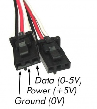
The Phidget Cable is a 3-pin, 0.100 inch pitch locking connector. Pictured here is a plug with the connections labelled. The connectors are commonly available - refer to the Analog Input Primer for manufacturer part numbers.
| Sensor Properties | |
|---|---|
| Sensor Type | Resistance |
| Controlled By | VoltageRatio Input |
| Sensor Output Type | Ratiometric |
| Resistance Min | 1 kΩ |
| Resistance Max | 21 kΩ |
| Optimal Measurement Resistance Min (@ 1kΩ) | 100 Ω |
| Optimal Measurement Resistance Max (@ 1kΩ) | 10 kΩ |
| Optimal Measurement Resistance Min (@ 21kΩ) | 2 kΩ |
| Optimal Measurement Resistance Max (@ 21kΩ) | 200 kΩ |
| Electrical Properties | |
| Current Consumption Max | 5 mA |
| Supply Voltage Min | 3 V DC |
| Supply Voltage Max | 5.3 V DC |
| Physical Properties | |
| Recommended Wire Size | 12 - 24 AWG |
| Operating Temperature Min | -40 °C |
| Operating Temperature Max | 105 °C |
| Customs Information | |
| Canadian HS Export Code | 8473.30.00 |
| American HTS Import Code | 8473.30.51.00 |
| Country of Origin | CN (China) |
| Date | Board Revision | Device Version | Comment |
|---|---|---|---|
| August 2007 | 0 | N/A | Product Release |
This device doesn't have an API of its own. It is controlled by opening a VoltageRatioInput channel on the Phidget that it's connected to. For a list of compatible Phidgets with VoltageRatio Inputs, see the Connection & Compatibility tab.
You can find details for the VoltageRatioInput API on the API tab for the Phidget that this adapter connects to.
| Product | Sensor Properties | ||
|---|---|---|---|
| Part Number | Price | Resistance Min | Resistance Max |
 Voltage Divider
|
$7.00 | 1 kΩ | 21 kΩ |